
Instruction Manual

Instruction Manual
D200158X012
4194S Controllers
December 2011
28
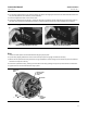
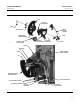
15. Install the proportional band knob (key 25) on the set point beam assembly (key 23).
16. Install the retaining clip (key 26) on the three posts on the proportional band knob.
17. Install the nozzle assembly (key 21) through the set point beam assembly (key 23), the proportional band knob
(key 25), and the retaining clip (key 26) into the cap, aligning the nozzle with the tab on the proportional band knob
(shown in figure 4‐5).
18. While holding the nozzle tubing (key 21) against the set point beam assembly (key 23), depress the retaining clip
(key 26), and install the E‐ring (key 27) into the E‐ring groove on the nozzle tubing assembly (key 18).
19. Inspect the O‐ring on the relay nozzle tubing assembly (key 18) and, replace it if necessary. Apply a suitable
lubricant to the O‐ring.
20. Install the relay nozzle tubing assembly (key 18) into the set point beam assembly.
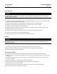
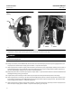
21. Adjust the proportional band between DIRECT and REVERSE. Do this by aligning the tab on the proportional band
knob with the hole in the set point beam assembly as shown in figure 4‐6.
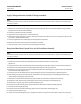
22. Position the proportional band knob, nozzle pivot and the set point beam assembly on the frame. Install the relay
nozzle tubing nut loosely into frame manifold while positioning the nozzle in the center of the flapper as shown in
figure 4‐7.
23. Insert the screw and washer (keys 19 and 20) into the relay nozzle tubing assembly (key 18). Refer to figure 4‐15.
24. Install the screw (key 19) through the frame (key 3) and into the relay nozzle tubing assembly (key 18). Tighten the
screw and make sure the nozzle remains centered on the flapper with the set point beam assembly snugly against
the relay nozzle tubing assembly.
25. Install the pivot of the set point pivot assembly (key 17) in the hole in the set point beam assembly (key 23).
26. Install the washer (key 20) on the screw (key 19).
27. Install the screw and washer (keys 19 and 20) through the frame (key 3) into the set point pivot assembly (key 23).
Do not tighten.
28. First, slide the beam assembly snugly toward the relay tubing assembly; then, slide the set point pivot assembly
(key 17) toward the set point beam until the cone lightly contacts the set point beam, and tighten the screw. The
proportional band knob should fall freely when the controller is in the upright position. If it does not, reposition the
set point pivot assembly (key 17) until the proportional band knob falls freely.
29. Tighten the nut on the relay nozzle tubing assembly (key 18), apply supply full pressure, and check for leaks.
Disconnect supply pressure.
30. Install the set point beam bias spring (key 28) into the frame bore and onto the spring seat on the set point beam
assembly (see figure 4‐5).
31. Attach link number 3 to the set point assembly (key 23). See figure 4‐12.
32. If the position of the set point beam shoe (see figure 4‐5) was changed relative to the set point beam assembly
(key 23) go to step 33. If the position of the set point beam shoe was not changed, go to step 53.
33. Connect supply pressure and regulated process differential pressure to the controller. Also, provide a means of
measuring controller output pressure.
34. Perform the procedures. Then, proceed as directed by the following note.
Note
For direct‐acting controllers, go to step 35. For reverse‐acting controllers, go to step 44.