
Instruction Manual

Instruction Manual
D200158X012
4194S Controllers
December 2011
53
5. Compress the switch body springs with the loader assembly (key 282), and bolt the switch (key 291) to the loader
assembly with the two screws (key 290).
6. Reconnect the tubing assembly (key 309).
7. Locate the lever spring (key 302) and the spring seat (key 301) on the switch lever (key 304) and position these
parts in the opening of the loader assembly (key 282).
8. Push the switch lever down, using the lever spring seat (key 301) and the lever assembly (key 297) to preload the
spring. Make sure the notch of the switch lever engages the pin of the lever assembly.
9. Drive in the groove pin (key 303) to hold the switch lever.
10. Replace the lever cover plate (key 305) and attach with two screws (key 288).
11. Perform the Assembly portion of the Replacing the Auto/Manual Station procedure.
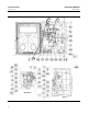
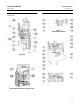
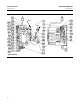
Replacing the Loader Range Spring, Diaphragm Assembly, Ball Seat, Tubing, and Ball
Refer to figure 5‐5 for key number location.
Disassembly
1. Perform steps 1 through 3 of the replacing case and cover procedure.
2. Remove the auto/manual station from the controller as described in steps 1 through 4 of the Replacing the
Auto/Manual Station procedure.
3. Remove the tubing assembly (key 309).
WARNING
To avoid personal injury caused by preload from the range spring (key 282), turn the loader knob (key 287)
counterclockwise (opposite to the arrow) to relieve pressure on the spring.
4. Loosen the four screws (key 289), and separate the upper loader assembly (key 282) and the lower loader assembly
(key 274).
5. Remove the loader range spring (key 283), range spring cup (key 284), and diaphragm assembly (key 281).
6. Remove the tube (key 278), ball seats (key 280) and ball (key 279).
Assembly
1. Turn the loader knob (key 287) counterclockwise to back the spring adjustment screw (key 285) all the way out to
eliminate loading the range spring.
2. Position the range spring cup (key 284), range spring (key 283), and the diaphragm assembly (key 281) on the
upper loader assembly (key 282).
3. Position the ball (key 279), the tube (key 278), and the ball seats (key 280) between the ears of the loader
assemblies (keys 282 and 274); position the diaphragm assembly (key 281) between the main halves of the loader
assemblies.
Note
The tube (key 278) must be well seated in the cups of the ball seats (key 280).