
Instruction Manual

Instruction Manual
D103425X012
546NS Transducer
April 2015
11
CAUTION
Reversing the DC input during the calibration cycle may result in product damage.
Note
During the calibration cycle, use care to avoid overshoot. In other words, if data is to be recorded at an 8.00 mA DC input while
moving upscale and you accidently pass 8.00 to some higher value, run the test again starting at step 7 with the three exercise
cycles. Do not reverse direction and move down scale to 8.00 mA DC.
10. After completing the calibration cycle and recording data, verify that all data is within ±0.75% accuracy limits. If not,
the transducer may need to be recalibrated to move the end points slightly to bring the entire calibration curve
within the accuracy limits.
Recalibration
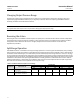
Table 5 shows typical recorded data where recalibration is necessary.
Table 5. Typical Calibration Data
TRANSDUCER INPUT ACTUAL OUTPUT PRESSURE TARGET OUTPUT PRESSURE
mA DC Bar Psig Bar Psig
12.00
16.00
20.00
16.00
12.00
8.00
4.00
8.00
12.00
0.612
0.823
1.035
0.828
0.617
0.413
0.207
0.409
0.618
8.89
11.95
15.02
12.02
8.96
6.00
3.01
5.95
8.97
0.620
0.826
1.033
0.826
0.620
0.413
0.206
0.413
0.620
9.00
12.00
15.00
12.00
9.00
6.00
3.00
6.00
9.00
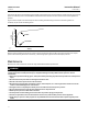
The 0.612 bar (8.89 psig) value at 12.00 mA DC is outside the accuracy limit of ±0.09 from the target value. This data
point can be raised by recalibrating the transducer and raising the end points enough to bring this low value within
-0.6 mbar (-0.09 psig) of 0.62 bar (9.00 psig). A reasonable recalibration would be 0.21 and 1.04 bar (3.05 and 15.05
psig) at 4.00 mA DC and 20.00 mA DC, respectively. Recalibrate the instrument and recheck the calibration data as
described in steps 7 through 10.
If the transducer remains outside of accuracy specifications after altering the calibration end points as much as
possible consult your Emerson Process Management sales office
.
For transducers inaccurate to less than 5 percent of output span, relay repair or replacement may correct the problem.
Refer to the alignment procedures in the Troubleshooting section to correct the operation of a faulty transducer. Also
check for air leaks at the tubing, nozzle, relay, and bellows.
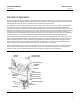
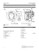
If the accuracy error is greater than 5 percent of output span, check the clearance between the armature and the coils.
These parts are referenced as key 40 and key 42, respectively, in the Parts List section. The armature and the white
plastic coil bobbin should be approximately 0.4 mm (1/64 inch) apart. If the parts are in contact, loosen the machine
screws that hold the bobbin and reposition the bobbin.