Instruction Manual 667 Size 80 and 100 Actuators D100311X012 May 2011 Fisherr 667 Diaphragm Actuators Size 80 and 100 Contents Introduction . . . . . . . . . . . . . . . . . . . . . . . . . . . . . . . . . 1 Scope of Manual . . . . . . . . . . . . . . . . . . . . . . . . . . . . . 1 Description . . . . . . . . . . . . . . . . . . . . . . . . . . . . . . . . . 2 Specifications . . . . . . . . . . . . . . . . . . . . . . . . . . . . . . . 2 Maximum Pressure Limitations . . . . . . . . . . . . . . . . .
Instruction Manual 667 Size 80 and 100 Actuators May 2011 D100311X012 Do not install, operate, or maintain 667 actuators without being fully trained and qualified in valve, actuator, and accessory installation, operation, and maintenance. To avoid personal injury or property damage, it is important to carefully read, understand, and follow all the contents of this manual, including all safety cautions and warnings.
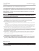
Instruction Manual 667 Size 80 and 100 Actuators D100311X012 May 2011 Figure 2. Schematic Representation of Fisher 667 Actuator DIAPHRAGM SPRING PUSHES DOWN AIR LIFTS ACTUATOR STEM AF3833‐A A6127 667 REVERSE‐ACTING DIAPHRAGM ACTUATOR Table 2. Maximum Pressure Limitations ACTUATOR SIZE 80 PRESSURE LIMITATIONS Maximum Casing Pressure for Actuator Sizing Maximum Excess Diaphragm Pressure bar 100 Standard Cast Iron Construction All Steel Construction 3.4 4.9 6.9 psig 50 70 100 bar 1.4 1.
667 Size 80 and 100 Actuators Instruction Manual May 2011 D100311X012 Because the actuator has traveled its specified travel, and the diaphragm head is physically stopped from movement, the force from any additional air pressure is transmitted to the diaphragm and diaphragm casings. The amount of air pressure that can be added once the actuator has traveled to the stops is limited by the resultant adverse effects that may occur.
Instruction Manual D100311X012 667 Size 80 and 100 Actuators May 2011 opening. If the valve is installed in a pipeline, the bottom flange (if one is used) can be removed and the valve plug pushed to the seat from the bottom opening. Reduce actuator loading pressure to extend the stem approximately 3.2 mm (1/8‐inch). CAUTION Incomplete engagement of either the valve stem or actuator stem in the stem connector can result in stripped threads or improper operation.
67 Size 80 and 100 Actuators May 2011 Instruction Manual D100311X012 When adjusting travel of a direct‐acting valve, put a slight pressure on the actuator diaphragm. This moves the valve plug off the seat, reducing the chance of damaging the valve plug or seat during adjustments. 1. Back the stem jam nuts (key 69, figures 6 and 7) away from the stem connector (key 31, figures 6 and 7), and slightly loosen the stem connector cap screws.
Instruction Manual 667 Size 80 and 100 Actuators D100311X012 May 2011 Remove the shroud plate (key 65, figure 7), and loosen the jam nut (key 26, figure 7). For small spring forces, adjustments can be made by rotating the adjusting nut (key 25, figure 7). Counterclockwise rotation (when viewed from the diaphragm casings) of the adjusting nut will increase the loading pressure required to start actuator stem travel, and clockwise rotation will decrease the pressure required to start travel.
Instruction Manual 667 Size 80 and 100 Actuators May 2011 D100311X012 D Do not remove the actuator from the valve while the valve is still pressurized. D Always wear protective gloves, clothing, and eyewear when performing any maintenance operations to avoid personal injury. D Disconnect any operating lines providing air pressure, electric power, or a control signal to the actuator. Be sure the actuator cannot suddenly open or close the valve.
Instruction Manual 667 Size 80 and 100 Actuators D100311X012 May 2011 actuator. Use lock‐out procedures to be sure that the above measures stay in effect while you work on the equipment. 2. Remove the tubing or piping from the connection in the top of the spring case adaptor (key 89). 3. If the actuator has a handwheel, rotate the handwheel to relieve all spring compression. 4. Remove the cover band (key 87). Insert a steel rod of approximately 12.
667 Size 80 and 100 Actuators Instruction Manual May 2011 D100311X012 b. Using a wrench on the wrench flats near the top of the stem and piston assembly, unscrew the stem and piston assembly from the actuator stem. c. Unscrew the cap screws (key 106), and remove the cylinder (key 93) and attached parts. 11. To disassemble snubber: a. Remove the retaining rings, cylinder heads, and stem and piston assembly (keys 95, 94, and 23). b. Replace packing and O‐rings (keys 118, 119, 96, 107, and 120). c.
Instruction Manual 667 Size 80 and 100 Actuators D100311X012 May 2011 Figure 4.
Instruction Manual 667 Size 80 and 100 Actuators May 2011 D100311X012 10. Position the upper diaphragm casing (key 1) on the diaphragm (key 3), and align the holes. Note When you replace actuator diaphragms in the field, take care to ensure the diaphragm casing cap screws are tightened to the proper load to prevent leakage, but do not crush the material. Perform the following tightening sequence with a manual torque wrench for size 80 and 100 actuators.
Instruction Manual 667 Size 80 and 100 Actuators D100311X012 May 2011 D Do not remove the actuator from the valve while the valve is still pressurized. D Always wear protective gloves, clothing, and eyewear when performing any maintenance operations to avoid personal injury. D Disconnect any operating lines providing air pressure, electric power, or a control signal to the actuator. Be sure the actuator cannot suddenly open or close the valve.
Instruction Manual 667 Size 80 and 100 Actuators May 2011 D100311X012 Figure 5.
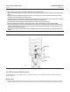
Instruction Manual 667 Size 80 and 100 Actuators D100311X012 May 2011 For Actuators Without the Top‐Loaded Option Disassembly Part names and locations are shown in figure 5. Size 100 actuator key number locations are shown in figure 7. 1. Unscrew the diaphragm casing cap screws and nuts (keys 13 and 14) and remove the upper diaphragm casing. 2. For actuators without a top‐mounted handwheel, unscrew and remove the travel stop cap screw (key 12), if one is used, and the hex nut (key 24). 3.
667 Size 80 and 100 Actuators May 2011 Instruction Manual D100311X012 6. Install the diaphragm backup plate, diaphragm retainer, diaphragm, upper diaphragm plate, and washer (keys 6, 5, 3, 4, and 37) on the actuator stem (key 144). CAUTION Install the diaphragm with the fabric side facing away from the spring. Smooth the edge of the diaphragm to avoid wrinkling and be careful that the diaphragm fold does not get pinched when the upper diaphragm casing (key 1) is installed.
Instruction Manual 667 Size 80 and 100 Actuators D100311X012 May 2011 15. Once completed, no more tightening is recommended. 16. For actuators with a top‐mounted handwheel (see figure 9), mount the gear case assembly (key 41) on the actuator using the cap screws (key 16). Install the hex nuts (key 47) and travel stop cap screw (if used) on the actuator stem extension (key 36). Install the gear case cover (key 53) with the cap screws (key 54). 17.
667 Size 80 and 100 Actuators Instruction Manual May 2011 D100311X012 3. Install the actuator stem assembly into the yoke assembly (key 67). Place a support under the stem to position the lower end of the stem 254 mm (10 inches) above the bottom surface of the actuator (actuator‐to‐bonnet joint). Note When installing the lower diaphragm casing, install O‐rings (key 70) into grooves found in the lower diaphragm casing before placing the casing on the yoke assembly.
Instruction Manual 667 Size 80 and 100 Actuators D100311X012 May 2011 8. Tighten the cap screws (key 13) in the following manner. The first four cap screws tightened should be diametrically opposed and 90 degrees apart. Tighten these four cap screws to 34 NSm (25 lbfSft). 9. Tighten the remaining cap screws in a clockwise, crisscross pattern to 34 NSm (25 lbfSft). 10. Repeat this procedure by tightening the four cap screws, diametrically opposed and 90 degrees apart, to a torque of 68 NSm (50 lbfSft).
667 Size 80 and 100 Actuators Instruction Manual May 2011 D100311X012 24. Once completed, no more tightening is recommended. 25. For actuators with a top‐mounted handwheel (see figure 9), mount the gear case assembly (key 41) on the actuator using cap screws (key 16). Install the hex nuts (key 47) and travel stop cap screw (if used) on the actuator stem extension (key 36). Install the gear case cover (key 53) with cap screws (key 54). 26.
Instruction Manual 667 Size 80 and 100 Actuators D100311X012 May 2011 7. The lower sleeve (key 123) has two screw holes in one end. Coat the sleeve threads with lithium grease lubricant, slide the end of the lower sleeve with the holes into the thrust bearing (key 43), turn the handwheel, and feed the sleeve through the worm gear. Continue turning the handwheel until the lower sleeve protrudes from the gear case. Fasten the travel stop indicator (key 126) to the sleeve with two machine screws (key 79).
667 Size 80 and 100 Actuators May 2011 5. 6. 7. 8. Instruction Manual D100311X012 Remove the retaining ring (key 60), and remove the handwheel. Remove front and back worm retainers (keys 48 and 49) and the bearings (key 50). Remove the worm shaft (key 51). Remove the power screw assembly (key 46) by placing a wrench on the double hex nuts (key 47) and unscrew the assembly from the actuator stem extension (key 36).
Instruction Manual 667 Size 80 and 100 Actuators D100311X012 May 2011 Parts Kits Key Actuator Repair Kit Parts kit includes keys 8, 9, and 70. Key Description Part Number Size 80 R667X000802 Parts List Note Part numbers are shown for recommended spares only. For part numbers not shown, contact your Emerson Process Management sales office.
Instruction Manual 667 Size 80 and 100 Actuators May 2011 D100311X012 Key 18 Spring, steel ACTUATOR SIZE 80 RANGE COMPRESSION RATE TRAVEL MAXIMUM LOAD PART NUMBER COLOR CODE 5630 1H747727082 Red 35,139 7900 1H747527082 Lt. Blue 2100 47,148 10,600 1H747327082 Yellow 455.3 2600 47,148 10,600 1H747627082 Lt. Green 542.58 3100 61,382 13,800 1H747027082 White bar psi mm Inches N/mm Lb/in N Lb 0.2‐1 3‐15 76 3 175.1 1000 25,042 0.2‐1 3‐15 51 2 0.3‐1.
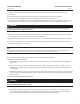
Instruction Manual 667 Size 80 and 100 Actuators D100311X012 May 2011 Figure 6. Size 80 Fisher 667 Actuator 50A8599‐C TOP‐LOADED ACTUATOR DETAIL APPLY LUB/SEALANT NOTE: KEYS 243, 244, 245, AND 246 ARE NOT SHOWN.
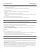
Instruction Manual 667 Size 80 and 100 Actuators May 2011 D100311X012 Figure 7. Size 100 Fisher 667 Actuator 56A9820‐B TOP‐LOADED ACTUATOR DETAIL 50A2623‐F APPLY LUB NOTES: THIS PART IS LOCATED 90_ TO FRONT OF POSITION SHOWN 1 2.
Instruction Manual 667 Size 80 and 100 Actuators D100311X012 May 2011 Figure 8.
667 Size 80 and 100 Actuators May 2011 Instruction Manual D100311X012 Figure 9. Size 100 Top‐Mounted Handwheel 50A2624‐F APPLY LUB Fisher is a mark owned by one of the companies in the Emerson Process Management business division of Emerson Electric Co. Emerson Process Management, Emerson, and the Emerson logo are trademarks and service marks of Emerson Electric Co. All other marks are the property of their respective owners.