
Instruction Manual

www.Fisher.com
Fisherr 249W Cageless Wafer Style Displacer
Sensor
Contents
Introduction 1.................................
Scope of Manual 1.............................
Description 2.................................
Type Number Description 3.....................
Educational Services 3.........................
Installation 4..................................
Installation on Top of Vessel 5...................
Installation with Displacer Cage
on Side of Vessel 5..........................
Mounting the Sensor on the Process
Vessel or Displacer Cage 9....................
Maintenance 11................................
Removing the Displacer and Stem 12.............
Replacing the Displacer, Cotter Spring,
Stem End Piece, and Displacer Spud 13.........
Replacing the Displacer Rod/Driver
Assembly 13...............................
Replacing the Torque Tube 14...................
Changing the Mounting from Left‐Hand to
Right‐Hand, or Vice Versa 16.................
Simulation of Process Conditions for Calibration
of Fisher Level Controllers and Transmitters 16......
Related Documents 17..........................
Parts Ordering 17...............................
Determining Displacer Stem Length 17...........
Parts List 18...................................
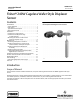
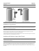
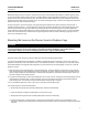
Figure 1. Fisher 249W Sensor with FIELDVUE™
DLC3010/DLC3020f Digital Level Controller
W8231
Introduction
Scope of Manual
This instruction manual includes maintenance, and parts ordering information for the 249W cageless wafer style
sensor.
Although the sensor is usually shipped with attached controller or transmitter, as shown in figure 1, this manual does
not include operation, installation, calibration, maintenance, or parts ordering information for the
controller/transmitter or for the complete unit. For this information, refer to the appropriate controller/ transmitter
instruction manual.
Instruction Manual
D102803X012
249W Sensor
December 2012