
Instruction Manual

Instruction Manual
D102803X012
249W Sensor
December 2012
17
Related Documents
This section lists other documents containing information related to the 249W level sensor. These documents include:
D 2500‐249 Pneumatic Controllers and Transmitters (Bulletin 34.2:2500)
D Fisher Level Controller and Transmitter Dimensions (Bulletin 34.2:249)
D Fisher L3 Pneumatic Level Controller (Bulletin 34.2:L3)
D Simulation of Process Conditions for Calibration of Fisher Level Controllers and Transmitters— Supplement to 249
Sensor Instruction Manuals (D103066X012)
D Bolt Torque Information— Supplement to 249 Sensor Instruction Manuals (D103220X012)
D Torque Tube Identification— Supplement to 249 Sensor Instruction Manuals (D103283X012)
All documents are available from your Emerson Process Management sales office. Also visit our website at
www.Fisher.com.
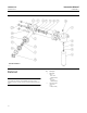
Parts Ordering
Whenever corresponding with your Emerson Process Management sales office about this equipment, always mention
the sensor serial number. Each sensor is assigned a serial number which is stamped on a nameplate (key 21) attached
to the torque tube arm. This same number also appears on the controller/transmitter nameplate when a complete
controller/transmitter/ sensor unit is shipped from the factory. When ordering a replacement part, be sure to include
the 11‐character part number from the following parts list.
WARNING
Use only genuine Fisher replacement parts. Components that are not supplied by Emerson Process Management should
not, under any circumstances, be used in any Fisher instrument. Use of components not supplied by Emerson Process
Management may void your warranty, might adversely affect the performance of the instrument, and could cause personal
injury or property damage.
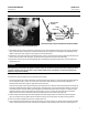
Determining Displacer Stem Length
When ordering a displacer stem, determine the displacer stem length from the G dimension in figure 6 for cage styles
3 and 4. For cage styles 1 and 2, the G dimension is typically 0, because the displacer is generally suspended from the
rod and driver assembly with no displacer stem required.
The stem length will be the G dimension rounded to the nearest 1/2‐inch increment. For example, if dimension G is
12.63 inches, round it to 12.5 inches. Specify a stem length of 12.5 inches. If dimension G is 9.44 inches, round it to 9.5
inches. Specify a stem length of 9.5 inches.
Stem lengths can be adjusted approximately ±0.25 inches for a more exact dimension. Stems are available in 1/2‐inch
increments from 2 to 54 inches.