
Instruction Manual

Instruction Manual
D102803X012
249W Sensor
December 2012
2
Do not install, operate, or maintain a 249W sensor and the attached controller or transmitter without being fully
trained and qualified in valve, actuator, and accessory installation, operation, and maintenance. To avoid personal
injury or property damage, it is important to carefully read, understand, and follow all of the contents of this manual,
including all safety cautions and warnings. If you have any questions about these instructions contact your Emerson
Process Management sales office before proceeding.
Description
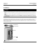
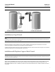
The 249W sensor is designed to measure liquid level, interface level, or density/specific gravity inside a process vessel.
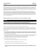
A torque tube assembly (figure 2) and displacer provide an indication of liquid level, interface level, or density/specific
gravity. The torque tube assembly consists of a hollow torque tube with a shaft welded inside it at one end and
protruding from it at the other end.
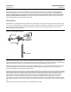
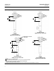
KNIFE EDGE
BEARING
DISPLACER ROD
W1800‐1
W8325
DISPLACER
TORQUE TUBE
Figure 2. Typical Cageless Displacer
The unconnected end of the tube is sealed by a gasket and clamped rigidly to the torque tube arm, permitting the
protruding end of the shaft to twist and therefore transmit rotary motion. This allows the interior of the torque tube to
remain at atmospheric pressure, thus eliminating packing and the disadvantages of packing friction.
The displacer always exerts a downward force on one end of the displacer rod. The other end of the displacer rod rests
on the knife‐edge of the driver bearing. A keyed shaft on the bearing end of the displacer fits into a socket on the
outside of the welded end of the torque tube assembly.
A change in liquid level, interface level, or density/specific gravity buoys up the displacer by a force equal to the weight
of the liquid displaced. Corresponding vertical movement of the displacer results in angular movement of the displacer
rod around the knife edge. Since the torque tube assembly is a torsional spring which supports the displacer and
determines the amount of movement of the displacer rod for a given displacement change, it will twist a specific
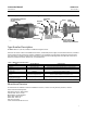
amount for each increment of buoyancy change. This rotation is brought through the torque tube arm by the
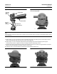
protruding rotary shaft. A controller or transmitter attached to the end of the rotary shaft converts the rotary motion
into varying pneumatic or electric signals. Figure 3 shows how the controller or transmitter mounts on the torque tube
arm.
Unless otherwise noted, all NACE references are to NACE MR0175-2002.