
Data Sheet

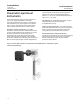


Level Instruments
D103219X012
Product Bulletin
11.2:Level
February 2015
11
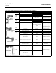
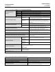
Table 10. Cage Connection Styles (also see figure 9)
Connection Types:
S = Screwed
F = Flanged
SW = Socket welding
Connection Locations:
Style 1 Style 2 Style 3 Style 4
Top and bottom Top and lower side Upper side and lower side Upper side and bottom
Example: F‐1 means flanged connections at the top and bottom of the cage.
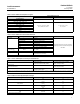
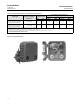
Figure 10. Mounting Positions—Caged Displacers
8
2
4
6
3
7
1
5
1
1
8
2
4
6
1
3
7
5
RIGHT‐HAND MOUNTING LEFT‐HAND MOUNTING
Note:
Mounting positions shown illustrate the DLC3010/DLC3020f. Mounting positions are also applicable to 2500 controllers/transmitters.
1 Position 5 is not available for NPS 2 CL300 and 600 249C.
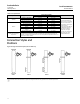
Figure 11. Mounting Positions—Wafer Style (Customer Supplied Cage)
CAGE WITH SIDE
CONNECTIONS
TOP‐MOUNTED
ON VESSEL
CAGE WITH TOP AND
BOTTOM CONNECTIONS
RIGHT‐HAND MOUNTING
LEFT‐HAND MOUNTING
Note:
Mounting positions shown illustrate the DLC3010/DLC3020f. These positions are also applicable to 2500 controllers/transmitters.