
Data Sheet

www.Fisher.com
Fisherr 249 Sensor, Level Controller, and
Transmitter Dimensions
This bulletin contains dimensional information for
Fisher
displacer‐type sensors and for controllers and
transmitters used with these sensors. Dimensions are
subject to change and certified dimensions should be
requested for construction projects. Some of the
abbreviations used in this document are as follows:
NPT = National Pipe Thread, NPS = Nominal Pipe Size,
FF = Flat Face Flange, RF = Raised Face Flange, and
RTJ = Ring Type Joint Flange.
Flange specification references are ASME B16.1 for
CL125 and 250 and ASME 16.5 for CL150, 300, 600,
900, 1500 and 2500.
Contents
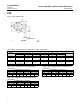
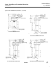
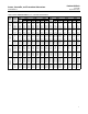
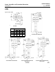
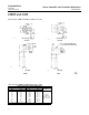
Caged Displacer for External Vessel Mounting
249: figure 1 and 2; tables 1, 2, 3, and 4
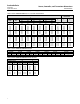
249B and 249BF: figure 3; tables 5, 6, 7, and 8
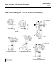
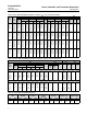
249C and 249K: figure 4; tables 9, 10, and 11
249L: figure 5
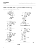
Cageless Displacer for Internal Vessel Mounting
Top Mounted.
249BP and 249P: figure 6; tables 12 and 13
249CP: figure 7; tables 14 and 15
Side Mounted.
249VS: figure 8, 9, 10, and 11
W8332
W7926
W8334
Cageless Displacer for Mounting on Customer
Supplied Cage or on Top of Vessel
249W: figure 12
Controllers and Transmitters
Fisher 2500 Controller / Transmitter: figure 13
FIELDVUEt DLC3010 / DLC3020f Digital Level
Controller: figure 14
Sensor, Controller, and Transmitter Dimensions
D200039X012
Product Bulletin
34.2:249
September 2014