Instruction Manual DLC3010 Digital Level Controller D102748X012 October 2014 Fisherr FIELDVUE™ DLC3010 Digital Level Controller This manual applies to: 3010 Device Type 1 Device Revision Hardware Revision 1 Firmware Revision 8 DD Revision 3 Contents Section 1 Introduction and Specifications . 3 Scope of Manual . . . . . . . . . . . . . . . . . . . . . . . . . . . . . . Conventions Used in this Manual . . . . . . . . . . . . . . . . Description . . . . . . . . . . . . . . . . . . . . . . . . . . . . . .
DLC3010 Digital Level Controller October 2014 Communications . . . . . . . . . . . . . . . . . . . . . . . . . . . . 53 Burst Mode . . . . . . . . . . . . . . . . . . . . . . . . . . . . . . . . 53 Burst Option . . . . . . . . . . . . . . . . . . . . . . . . . . . . . . . 53 Calibration . . . . . . . . . . . . . . . . . . . . . . . . . . . . . . . . . . 54 Introduction: Calibration of Smart Instruments . . 54 Primary . . . . . . . . . . . . . . . . . . . . . . . . . . . . . . . . . . .
Instruction Manual Introduction and Specifications D102748X012 October 2014 Section 1 Introduction and Specifications Scope of Manual1‐1‐ This instruction manual includes specifications, installation, operating, and maintenance information for FIELDVUE DLC3010 digital level controllers. This instruction manual supports the 475 or 375 Field Communicator with device description revision 3, used with DLC3010 instruments with firmware revision 8.
Introduction and Specifications October 2014 Instruction Manual D102748X012 displacer, which rotates the torque tube shaft. This rotary motion is applied to the digital level controller, transformed to an electrical signal and digitized. The digital signal is compensated and processed per user configuration requirements, and converted back to a 4‐20 mA analog electrical signal. The resulting current output signal is sent to an indicating or final control element. Figure 1‐1.
Instruction Manual Introduction and Specifications D102748X012 October 2014 Related Documents Other documents containing information related to the DLC3010 digital level controller and 249 sensors include: D Bulletin 11.
Instruction Manual Introduction and Specifications D102748X012 October 2014 Table 1‐1. DLC3010 Digital Level Controller Specifications Performance Available Configurations DLC3010 Digital Level Controller: Mounts on caged and cageless 249 sensors. See tables 1‐6 and 1‐7 and sensor description. Performance Criteria DLC3010 Digital Level Controller(1) w/ NPS 3 249W, Using a 14‐inch Displacer w/ All Other 249 Sensors Function: Transmitter Independent Linearity $0.25% of output span $0.
Instruction Manual Introduction and Specifications D102748X012 October 2014 Table 1‐1. DLC3010 Digital Level Controller Specifications (continued) LCD Meter Indications Electromagnetic Compatibility LCD meter indicates analog output on a percent scale bar graph. The meter also can be configured to display: Process variable in engineering units only. Percent range only.
Instruction Manual Introduction and Specifications D102748X012 October 2014 Table 1‐1. DLC3010 Digital Level Controller Specifications (continued) encapsulated printed wiring boards; Neodymium Iron Boron Magnets Minimum Differential Specific Gravity (continued) See 249 sensor specifications for standard displacer volumes and standard wall torque tubes. Standard volume for 249C and 249CP sensors is ∼980 cm3 (60 in3), most others have standard volume of ∼1640 cm3 (100 in3).
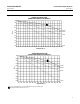
Instruction Manual Introduction and Specifications D102748X012 October 2014 Figure 1‐2. Theoretical Reversible Temperature Effect on Common Torque Tube Materials TORQUE RATE REDUCTION (NORMALIZED MODULUS OF RIGIDITY) 1.00 0.98 1 0.96 0.94 N05500 N06600 Gnorm 0.92 0.90 N10276 0.88 0.86 0.84 0.82 S31600 0.80 20 40 60 80 100 120 140 160 180 200 220 240 260 280 300 320 340 360 380 400 420 TEMPERATURE (_C) TORQUE RATE REDUCTION (NORMALIZED MODULUS OF RIGIDITY) 1.00 0.98 1 0.96 0.94 Gnorm 0.
Instruction Manual Introduction and Specifications D102748X012 October 2014 Table 1‐3.
Instruction Manual Introduction and Specifications D102748X012 October 2014 Table 1‐6.
Instruction Manual Introduction and Specifications D102748X012 October 2014 Figure 1‐3.
Instruction Manual D102748X012 Installation October 2014 Section 2 Installation2-2This section contains digital level controller installation information including an installation flowchart (figure 2‐1), mounting and electrical installation information, and a discussion of failure mode jumpers. Configuration: On the Bench or in the Loop Configure the digital level controller before or after installation.
Instruction Manual Installation D102748X012 October 2014 Figure 2‐1.
Instruction Manual D102748X012 Installation October 2014 4. If the controller was shipped alone, the access handle will be in the locked position. All Mounting, Coupling and Calibration procedures must be performed. The access handle includes a retaining set screw, as shown in figures 2‐4 and 2‐6. The screw is driven in to contact the spring plate in the handle assembly before shipping. It secures the handle in the desired position during shipping and operation.
Instruction Manual Installation D102748X012 October 2014 Figure 2‐2. Typical Caged Sensor Mounting Figure 2‐3. Typical Cageless Sensor Mounting A3788‐1 A3789‐1 Digital Level Controller Orientation Mount the digital level controller with the torque tube shaft clamp access hole (see figure 2‐4) pointing downward to allow accumulated moisture drainage. Figure 2‐4.
Instruction Manual Installation D102748X012 October 2014 Note If alternate drainage is provided by the user, and a small performance loss is acceptable, the instrument could be mounted in 90 degree rotational increments around the pilot shaft axis. The LCD meter may be rotated in 90 degree increments to accommodate this. The digital level controller and torque tube arm are attached to the sensor either to the left or right of the displacer, as shown in figure 2‐5.
Instruction Manual Installation D102748X012 October 2014 Mounting the Digital Level Controller on a 249 Sensor Refer to figure 2‐4 unless otherwise indicated. 1. If the set‐screw in the access handle (figure 2‐6) is driven against the spring plate, back it out until the head is flush with the outer surface of the handle, using a 2 mm hex key. Slide the access handle to the locked position to expose the access hole.
Instruction Manual Installation D102748X012 October 2014 PROCESS TEMPERATURE (_F) AMBIENT TEMPERATURE (_C) -40 800 -30 -20 -10 0 10 20 30 40 50 TOO HOT HEAT INSULATOR REQUIRED 400 70 60 80 425 400 300 200 100 -325 -40 0 NO HEAT INSULATOR NECESSARY 0 1 -100 TOO COLD -20 HEAT INSULATOR REQUIRED 0 20 40 60 -200 80 100 120 140 160 176 PROCESS TEMPERATURE (_C) Figure 2‐7.
Instruction Manual Installation D102748X012 October 2014 Electrical Connections WARNING Select wiring and/or cable glands that are rated for the environment of use (such as hazardous area, ingress protection and temperature). Failure to use properly rated wiring and/or cable glands can result in personal injury or property damage from fire or explosion. Wiring connections must be in accordance with local, regional, and national codes for any given hazardous area approval.
Instruction Manual Installation D102748X012 October 2014 determine the required lift‐off voltage. If you know your total loop resistance you can determine the lift‐off voltage. If you know the available supply voltage, you can determine the maximum allowable loop resistance. Figure 2‐10. Power Supply Requirements and Load Resistance Maximum Load = 43.5 X (Available Supply Voltage - 12.
Instruction Manual Installation D102748X012 October 2014 Figure 2‐11. Digital Level Controller Terminal Box 4‐20 mA LOOP CONNECTIONS TEST CONNECTIONS 1/2 NPT CONDUIT CONNECTION RTD CONNECTIONS 1/2 NPT CONDUIT CONNECTION INTERNAL GROUND CONNECTION FRONT VIEW EXTERNAL GROUND CONNECTION REAR VIEW W8041 CAUTION Do not apply loop power across the T and + terminals. This can destroy the 1 Ohm sense resistor in the terminal box. Do not apply loop power across the Rs and — terminals.
Instruction Manual D102748X012 Installation October 2014 Power/Current Loop Connections Use ordinary copper wire of sufficient size to ensure that the voltage across the digital level controller terminals does not go below 12.0 volts DC. Connect the current signal leads as shown in figure 2‐9. After making connections, recheck the polarity and correctness of connections, then turn the power on. RTD Connections An RTD that senses process temperatures may be connected to the digital level controller.
Instruction Manual Installation D102748X012 October 2014 Test connections inside the terminal box can be used to measure loop current across an internal 1 ohm resistor. 1. Remove the terminal box cap. 2. Adjust the test meter to measure a range of 0.001 to 0.1 volts. 3. Connect the positive lead of the test meter to the + connection and the negative lead to the T connection inside the terminal box. 4.
Instruction Manual D102748X012 Installation October 2014 Alarm Jumper Each digital level controller continuously monitors its own performance during normal operation. This automatic diagnostic routine is a timed series of checks repeated continuously. If diagnostics detect a failure in the electronics, the instrument drives its output to either below 3.70 mA or above 22.5 mA, depending on the position (HI/LO) of the alarm jumper.
Instruction Manual Installation D102748X012 October 2014 Loop Test Field Communicator Service Tools > Maintenance > Tests > Loop Test (3-3-1-1) or (3-3-1-2) if LCD Configuration is installed Loop test can be used to verify the controller output, the integrity of the loop, and the operations of any recorders or similar devices installed in the loop. To initiate a loop test, perform the following procedure: 1. Connect a reference meter to the controller.
Instruction Manual Installation D102748X012 October 2014 Installation in Conjunction with a Rosemount 333 HART Tri‐Loop HART‐to‐Analog Signal Converter Use the DLC3010 digital level controller in operation with a Rosemount 333 HART Tri-Loop HART‐to‐Analog Signal Converter to acquire an independent 4‐20 mA analog output signal for the process variable, % range, electronics temperature, and process temperature.
Instruction Manual Installation D102748X012 October 2014 Commissioning the Digital Level Controller for use with the HART Tri‐Loop To prepare the digital level controller for use with a 333 HART Tri‐Loop, you must configure the digital level controller to burst mode, and select the dynamic variables to burst. In burst mode, the digital level controller provides digital information to the HART Tri‐Loop HART‐to‐Analog Signal Converter.
Instruction Manual D102748X012 Overview October 2014 Section 3 Overview3-3Overview Field Communicator Overview (1) Device Status Good there are no active alerts and instrument is In Service Failed a failed alert is active Maintenance a configured maintenance alert is active and a failed alert is turned on Advisory a configured advisory alert is active and configured failed or a maintenance alert is turned on Comm Status Polled communication with Digital Level Controller is established.
Overview Instruction Manual October 2014 D102748X012 Process Temperature Proc Temp Source— Manual or RTD Proc Temp— indicates the process temperature. Device Information Identification Follow the prompts on the Field Communicator display to view the following information. D HART Tag— a unique name (up to eight characters) that identifies the physical instrument. D Distributor— identifies the distributor of the instrument. D Model— identifies the instrument model; ie. DLC3010.
Instruction Manual D102748X012 Overview October 2014 Alarm Type and Security Alarm Type D Alarm Jumper— displays the position of the hardware alarm jumper, either high current or low current. D Display Alert/Saturation Level Security D Write Lock D Write Lock Setup To setup and calibrate the instrument, write lock must be set to Writes Enabled. (Write Lock is reset by a power cycle. If you have just powered up the instrument Writes will be enabled by default.
Overview October 2014 32 Instruction Manual D102748X012
Instruction Manual D102748X012 Configuration October 2014 Section 4 Configuration and Calibration 4-4Initial Setup If a DLC3010 digital level controller ships from the factory mounted on a 249 sensor, initial setup and calibration is not necessary. The factory enters the sensor data, couples the instrument to the sensor, and calibrates the instrument and sensor combination.
Instruction Manual Configuration October 2014 D102748X012 D Instrument mounting (right or left of displacer) D Measurement Application (level, interface, or density) Configuration Advice Guided Setup directs you through initialization of configuration data needed for proper operation. When the instrument comes out of the box, the default dimensions are set for the most common Fisher 249 construction, so if any data is unknown, it is generally safe to accept the defaults.
Instruction Manual Configuration D102748X012 October 2014 Figure 4‐1. Example Sensor Nameplate SENSOR TYPE DISPLACER PRESSURE RATING ASSEMBLY PRESSURE RATING DISPLACER WEIGHT 76543210 249B PSI 285/100 F 1500 PSI 2 x 32 INCHES WCB STL 103 CU‐IN 4 3/4 LBS MONEL 316 SST K MONEL/STD DISPLACER MATERIAL TRIM MATERIAL DISPLACER VOLUME 23A1725‐E sht 1 E0366 ASSEMBLY MATERIAL TORQUE TUBE MATERIAL DISPLACER SIZE (DIAMETER X LENGTH) Table 4‐1.
Instruction Manual Configuration October 2014 D102748X012 4. Select the measurement application (level, interface, or density). Note For interface applications, if the 249 is not installed on a vessel, or if the cage can be isolated, calibrate the instrument with weights, water, or other standard test fluid, in level mode. After calibrating in level mode, the instrument can be switched to interface mode. Then, enter the actual process fluid specific gravity(s) and range values.
Instruction Manual D102748X012 Configuration October 2014 PV alert thresholds are initialized at 100%, 95%, 5% and 0% span. PV alert deadband is initialized to 0.5% span. PV alerts are all disabled. Temperature alerts are enabled. D If Density mode was chosen, setup is complete. D If Interface or Density mode was chosen, you are prompted to enter the specific gravity of the process fluid (if interface mode, the specific gravities of the upper and lower process fluids).
Configuration October 2014 Instruction Manual D102748X012 Coupling If the digital level controller is not already coupled to the sensor, perform the following procedure to couple the digital level controller to the sensor. 1. Slide the access handle to the locked position to expose the access hole. Press on the back of the handle as shown in figure 2‐4 then slide the handle toward the front of the unit. Be sure the locking handle drops into the detent. 2.
Instruction Manual D102748X012 Configuration October 2014 Manual Setup The DLC3010 digital level controller has the capability to communicate via the HART protocol. This section describes the advanced features that can be accessed with the Field Communicator. Note Changing setup parameters may require enabling writing to the instrument with the Field Communicator (Overview > Device Information > Alarm Type and Security > Security > Write Lock Setup).
Configuration October 2014 Instruction Manual D102748X012 D Driver Rod Length— Enter the displacer rod length. The displacer rod length depends upon the sensor type. For a 249 sensor, obtain the displacer rod length from table 4‐1 or from the Field Communicator Help. Refer to figure 4‐2 to physically measure this value. Torque Tube Follow the prompts on the Field Communicator to enter torque tube data. D Torque Rate— Displays the torque rate currently stored in the instrument.
Instruction Manual Configuration D102748X012 October 2014 Variables Field Communicator Configure > Manual Setup > Variables (2-2-2) Primary Variables Follow the prompts on the Field Communicator to view or edit Primary Variable information. D PV is— Display the PV currently stored in the instrument. Change PV— Follow the prompts to change the PV. Select Level Units if the PV is level, Interface Units if the PV is Interface, or Density Units if the PV is Density.
Configuration October 2014 Instruction Manual D102748X012 Sensor Limits Follow the prompts on the Field Communicator to view sensor limit information. D Upper Sensor Limit— Indicates the maximum usable value for the Upper Range Value. D Lower Sensor Limit— Indicates the minimum usable value for the Lower Range Value. D Minimum Span— Difference between the Upper Range Value and the Lower Range Value below which amplification of instrument errors may become a concern.
Instruction Manual D102748X012 Configuration October 2014 PV Damping PV Damping changes the response time of the controller to smooth variations in output readings caused by rapid changes in input. Determine the appropriate damping setting based on the necessary response time, signal stability, and other requirements of the loop dynamics of your system. The default damping value is 0.2 seconds. and can be reset to any value between 0 and 16 seconds in 0.1 second increments.
Instruction Manual Configuration October 2014 D102748X012 Table 4‐2. Example Specific Gravity vs Temperature Table for Saturated Water Temperature Data Point _C _F Specific Gravity 1 2 3 4 5 26.7 93.3 176.7 248.9 304.4 80.0 200.0 350.0 480.0 580.0 0.9985 0.9655 0.8935 0.8040 0.7057 6 7 8 9 10 337.8 354.4 365.6 371.1 374.7 640.0 670.0 690.0 700.0 706.5 0.6197 0.5570 0.4940 0.4390 0.3157 Figure 4‐4. Example Saturated Water Curve Plotted with Values from Table 4‐2 TEMPERATURE _C -18 1.
Instruction Manual Configuration D102748X012 October 2014 gravity value, select Single Point and enter the specific gravity value. To display or enter values in the tables, select Table of SG vs T. The Field Communicator begins by prompting for the temperature of the first pair in the lower table. After entering the temperature for the first pair, press ENTER. Enter the specific gravity for the first pair and press ENTER. The Field Communicator then prompts for the temperature for the second pair.
Instruction Manual Configuration October 2014 D102748X012 Figure 4‐5. Example Saturated Steam Curve Plotted from Values in Table 4‐3 TEMPERATURE _C 100 -18 0.35 200 300 375 SPECIFIC GRAVITY 0.30 0.25 0.20 0.15 0.10 0.05 0.
Instruction Manual D102748X012 Configuration October 2014 D Date— Date is a user‐defined variable that provides a place to save the date of the last revision of configuration or calibration information. It has no impact on the operation of the controller or Field Communicator. Enter a date with the format MM/DD/YY. D Descriptor— The Descriptor provides a longer user‐defined electronic label to assist with more specific controller identification that is available with the HART tag.
Instruction Manual Configuration October 2014 D102748X012 If PV/Proc Temp or PV/% Range is selected, the display alternates every two seconds between the selected readings. The meter also simultaneously displays the analog output signal using a percent of scale bar graph around the perimeter of the display face as shown in figure 4‐6, no matter what display type is selected. Figure 4‐6.
Instruction Manual D102748X012 Configuration October 2014 Alert Setup The following menus are available for configuring Alerts. Primary Variable Field Communicator Configure > Alert Setup > Primary Variable (2-3-1) Follow the prompts on the Field Communicator display to view or edit the following primary variable alerts. Primary Variable Hi D Hi Alert PV Hi Alert Enable— On or Off. PV High Alert Enable activates checking the primary variable against the PV High Alert limit.
Instruction Manual Configuration October 2014 D102748X012 PV Lo Alert Threshold— Primary Variable Lo Alert Threshold is the value of the primary variable, in engineering units, which, when exceeded, sets the Primary Variable Low Alert. PV Lo Alert Threshold— Method to change the PV Lo Alert Threshold D Lo Lo Alert PV LoLo Alert Enable— On or Off. PV Lo Lo Alert Enable activates checking the primary variable against the PV Lo Lo Alert limit.
Instruction Manual D102748X012 Configuration October 2014 Temperature Field Communicator Configure > Alert Setup > Temperature (2-3-2) Follow the prompts on the Field Communicator display to set the following temperature alerts. Instrument Temperature D Hi Alert Inst Temp Hi Alert Enable— On or Off. Instrument Temperature High Alert Enable activates checking of the instrument temperature against the Instrument Temperature High Alert Threshold.
Instruction Manual Configuration October 2014 D102748X012 Proc Temp Lo Alert Threshold— Process Temperature Low Alert Threshold is the process variable temperature, in temperature units, which, when exceeded, will set the Temperature Low Alert. D Proc Temp— Displays the process temperature stored in the instrument. D Proc Temp Offset— Bias to improve the accuracy of the (RTD) temperature measurement used to provide compensation for processtemperaturerelated density changes.
Instruction Manual Configuration D102748X012 October 2014 Communications Field Communicator Configure > Communications > Burst Mode (2-4-1) or Burst Option (2-4-2) Burst Mode Enabling burst mode provides continuous communication from the digital level controller. Burst mode applies only to the transmission of burst mode data and does not affect the way other data is accessed. Depending upon the burst option selected, the digital level controller will burst the variables as shown in table 2‐1.
Instruction Manual Configuration October 2014 D102748X012 Calibration Introduction: Calibration of Smart Instruments Analog instruments generally have only one interface that can be calibrated by the user. A zero and span output calibration is normally performed at the corresponding two input conditions. Zero/Span calibration is very simple to use, but provides little versatility.
Instruction Manual D102748X012 Configuration October 2014 Full Calibration Field Communicator Configure > Calibration > Primary > Full Calibration (2-5-1-2) Full Calibration operations compute the sensor gain and offset from two independent observations of process data points. They are appropriate for cases where the two input conditions can be established relatively quickly in one session.
Configuration October 2014 Instruction Manual D102748X012 The sensor torque rate is now calibrated. Be sure to verify that there is no bias in the PV calculation and that the upper and lower range values are correct before returning the loop to automatic control. Weight Calibration This procedure may be used on the bench or with a calibration jig that is capable of applying a mechanical force to the driver rod to simulate displacer buoyancy changes.
Instruction Manual D102748X012 Configuration October 2014 Observations of the sight glass or other independent measurements may be logged against DLC3010 outputs over time. The ratio of the independent‐observable process changes to the DLC3010 output changes may then be used as a scale factor to modify the theoretical torque rate stored in the instrument. After each gain adjustment, a new zero trim will be required.
Instruction Manual Configuration October 2014 D102748X012 and able to be measured independently. Configuration data must contain density of calibration fluid, displacer volume, and driver rod length. Before calibration, use the Configure > Manual Setup >Sensor menu to verify that all sensor and compensation data match the calibration conditions.
Instruction Manual Configuration D102748X012 October 2014 Trim Instrument Temperature Follow the prompts on the Field Communicator to trim the instrument temperature. Trim Process Temperature Trim Process Temperature is available if the Process Temperature Source is not Manual. Follow the prompts on the Field Communicator to trim the process temperature.
Configuration Instruction Manual October 2014 D102748X012 8. If the reference meter reading equals 4 mA or the low output value, select Yes and continue to step 9. If not, select No and return to step 7. 9. The Field Communicator commands the instrument to set its output to 20 mA or the high output value. 10. Enter the reading from the reference meter. 11. If the reference meter reading equals 20 mA or the high output value, select Yes and continue to step 12. If not, select No and return to step 10.
Instruction Manual D102748X012 Configuration October 2014 After the initial calibration: For a level application— Go to the Sensor Compensation menu and use the 'Enter constant SG' item to configure the instrument for the target process fluid density. For an interface application— Change the PV mode to Interface, verify or adjust the range values presented by the Change PV mode procedure, and then use 'Enter constant SG' to configure the instrument for the SGs of each of the target process fluids.
Configuration Instruction Manual October 2014 D102748X012 The calibration process flows as follows: D Change the PV mode to Level. D Set the Level Offset to zero. D Set the Range Values to: LRV = 0.0, URV = displacer length. D Capture Zero at the lowest process condition (that is, with the displacer completely submerged in the fluid of the lowest density NOT dry). D Set Specific Gravity to the difference between the SGs of the two fluids (for example, if SG_upper = 0.87 and SG_lower = 1.
Instruction Manual Configuration D102748X012 October 2014 Density Applications - with Standard Displacer and Torque Tube Note When you change 'PV is' from level or interface to density, the range values will be initialized to 0.1 and 1.0 SGU. You may edit the range values according to the specify gravity unit. It is necessary to back out of Manual Setup and reenter the Manual Setup menu to see the changes being refreshed.
Configuration Instruction Manual October 2014 D102748X012 1. Determine all the information you can about the 249 hardware: 249 type, mounting sense (controller to the right or left of displacer), torque tube material and wall thickness, displacer volume, weight, length, and driver rod length. (the driver rod length is not the suspension rod length, but the horizontal distance between the centerline of the displacer and the centerline of the torque tube).
Instruction Manual D102748X012 Configuration October 2014 These steps will provide an approximate PV calibration to get a system operational. Further refinements can then be made when it is possible to manipulate and observe the level and instrument output. Excessive Mechanical Gain If the displacer/torque tube sizing provides more than 4.4 degrees of torque tube rotation for a full span change in process input, It may be difficult to obtain a valid calibration with the normal coupling procedure.
Configuration October 2014 Instruction Manual D102748X012 sensitivity to the knowledge of a fluid density is maximum at the process condition where that fluid covers all of the displacer, and zero at the opposite extreme process condition. If the fluid density changes are batch‐related or very gradual, it may be practical to keep track of the SG of the fluid and periodically reconfigure the transmitter memory to match the actual process condition.
Instruction Manual D102748X012 Service Tools October 2014 Section 5 Service Tools5-5Active Alerts Field Communicator Service Tools > Active Alerts (3-1) Visible if an alert is not active No Active Alerts Visible if an alert is active Refresh Alerts—the following menu/methods will be visible only if the associated alert is active: D F: Process Temperature Signal Failed - When active, indicates the process temperature sensor (RTD) reading has exceeded the hardcoded limits (<10 ohms or >320 ohms).
Instruction Manual Service Tools D102748X012 October 2014 D A: PV HiHi Alert - When active, indicates that the Process Variable has exceeded the value of the Process Variable High High Alert Threshold. Analog Output set to jumperselected alarm current. D A: PV Hi Alert - When active, indicates that the Process Variable has exceeded the value of the Process Variable High Alert Threshold. D A: PV Out of Limits - Primary Variable value is beyond its operating limit.
Instruction Manual Service Tools D102748X012 October 2014 150 150 130 130 110 110 90 90 PV (% RANGE) PV (% RANGE) Figure 5‐1.
Instruction Manual Service Tools D102748X012 October 2014 Maintenance Tests Field Communicator Service Tools > Maintenance > Tests (3-3-1-1) LCD Test— only visible if LCD Configuration is installed The meter activates all segments immediately after power‐up, during a digital level controller self‐test, or during a master reset sent by a host supporting HART communications.
Instruction Manual D102748X012 Maintenance & Troubleshooting October 2014 Section 6 Maintenance & Troubleshooting6‐6‐ The DLC3010 digital level controller features a modular design for easy maintenance. If you suspect a malfunction, check for an external cause before performing the diagnostics described in this section. Sensor parts are subject to normal wear and must be inspected and replaced as necessary. For sensor maintenance information, refer to the appropriate sensor instruction manual.
Instruction Manual Maintenance & Troubleshooting D102748X012 October 2014 Figure 6‐1. LCD Meter Diagnostic Display ANALOG DISPLAY OF OUTPUT PROCESS VARIABLE VALUE DIAGNOSTIC MESSAGE E0380 MODE D FAIL HDWR— This message indicates the existence of one or more of the following conditions: —The primary sensor input conversion is out of range. —The primary sensor drive current is out of range. —The internal reference voltage for controlling the loop current is out of range.
Instruction Manual Maintenance & Troubleshooting October 2014 D102748X012 Table 6‐1. Troubleshooting Symptom Potential Source Loop Wiring Analog Output is within valid range but Instrument does not communicate with Field Communicator Terminal Box Corrective Action 1. Check resistance between the power supply and the Field Communicator connection. The net resistance in the loop must be between 230 and 1100 Ohms for HART communication. 2. Check for adequate voltage to the digital level controller.
Maintenance & Troubleshooting Instruction Manual October 2014 D102748X012 Test Terminals Test connections inside the terminal box can be used to measure loop current. These terminals are across an internal 1 ohm resistor that is in series with the loop. 1. Remove the terminal box cap. 2. Adjust the test meter to measure a range of 0.001 to 0.1 volts. 3. Connect the positive lead of the test meter to the + connection and the negative lead to the T connection inside the terminal box. 4.
Instruction Manual Maintenance & Troubleshooting October 2014 D102748X012 Table 6‐2. Tools Required Tool Size Usage Keys Handle Cover‐lock set screws 31 20 Hex Key 2 mm Hex Key 2.
Maintenance & Troubleshooting Instruction Manual October 2014 D102748X012 7. When re‐installing the digital level controller, follow the appropriate procedure outlined in the Installation section. Also setup the digital level controller as described in the Initial Setup section. 249 Sensor in High Temperature Applications 1. Loosen the set screw (key 31) in the terminal box cover assembly (key 6) so that the cover can be unscrewed from the terminal box. 2.
Instruction Manual Maintenance & Troubleshooting October 2014 D102748X012 The digital level controller is designed with a dual‐compartment housing; one compartment contains the LCD meter and Electronics Module; the other contains all wiring terminals and the communication receptacles. The LCD meter is located in the compartment opposite the wiring terminals, as shown in figure 6‐2. Figure 6‐2.
Maintenance & Troubleshooting October 2014 Instruction Manual D102748X012 the long meter screws into the two holes on the meter to coincide with the appropriate holes on the Electronics Module. 3. Attach the meter to the interconnection pins. Thread the long meter screws into the holes on the Electronics Module and tighten to secure the meter. 4. Note the position of the alarm jumper on the LCD meter removed from the digital level controller.
Instruction Manual D102748X012 Maintenance & Troubleshooting October 2014 1. Carefully insert the Electronics Module to mate the interconnecting pins with the receptacles on the Transducer housing. CAUTION To prevent damage to the interconnecting pins when installing the Electronics Module, use the guide pins to insert the Electronics Module straight onto the Transducer housing receptacles without twisting or turning. 2. Tighten the two mounting screws. Replace the LCD meter assembly. 3.
Maintenance & Troubleshooting Instruction Manual October 2014 D102748X012 1. Apply sealant to the O‐ring (key 27) and install the O‐ring over the stem of the terminal box as shown in figure 7‐3. 2. Orient the terminal box so that the connectors engage properly, and carefully insert the terminal box into the transducer housing until the O‐ring is seated. CAUTION To avoid damaging the mating pins in the Transducer housing, ensure that the guiding mechanism is engaged properly before applying force. 3.
Instruction Manual Maintenance & Troubleshooting October 2014 D102748X012 Figure 6‐3. Installing Inner Guide and Access Handle Assembly SCREWS (KEY 13) HANDLE ASSEMBLY (KEY 12) VENT HOLES LUBRICATE THIS SURFACE LUBRICATE THIS SURFACE VENT HOLE TRANSDUCER HOUSING INNER GUIDE (KEY 11) E0381 ZERO LOCKING PIN ACCESS HOLE 6.
Maintenance & Troubleshooting October 2014 Instruction Manual D102748X012 1. Remove the digital level controller from the sensor as described in Removing the Digital Level Controller from the Sensor. 2. Loosen and remove the hex nuts (key 34) from the studs (key 33) and remove the adapter ring (key 32). 3. Remove the coupling shield (key 16) by removing the two screws (key 13). Take care not to drop the screws into the lever assembly compartment where they will be attracted by the magnets. 4.
Instruction Manual Maintenance & Troubleshooting D102748X012 October 2014 Packing for Shipment If it becomes necessary to return the unit for repair or diagnosis, contact your Emerson Process Management sales office for returned goods information. CAUTION Lock the lever assembly when shipping the stand‐alone instrument, to prevent damage to the flexure. Use the original shipping carton if possible.
Maintenance & Troubleshooting October 2014 84 Instruction Manual D102748X012
Instruction Manual Parts D102748X012 October 2014 Section 7 Parts7‐7‐ Parts Ordering Whenever corresponding with your Emerson Process Management sales office about this equipment, always mention the controller serial number. When ordering replacement parts, refer to the 11‐character part number of each required part as found in the following parts list. Parts that do not show part numbers are not orderable. WARNING Use only genuine Fisher replacement parts.
Instruction Manual Parts D102748X012 October 2014 Parts List Key Description Part Number Key 3 4 5* Note Part numbers are shown for recommended spares only. For part numbers not shown, contact your Emerson Process Management sales office.
Instruction Manual Parts D102748X012 Key October 2014 Description Part Number Transducer Assembly (figure 7‐2) 11 12 13 14 15* 16 17 Inner Guide, aluminum Handle Ass'y aluminum/SST Screw, hex socket, 18‐8 SST (4 req'd) Screw, cap, 18‐8 SST Lever Assembly, aluminum/SST/NdFeB/CS Coupling Shield, 18‐8 SST Ring, align/clamp 38B5509X042 Key Description 19 20 31 67 Machine Screw, pan head Set Screw, 18‐8 SST(2) Set Screw, hex socket, 18‐8 SST(2) Thread Locking adhesive (medium strength) (not furnish
Instruction Manual Parts D102748X012 October 2014 Figure 7‐3. Terminal Box Assembly A SECTION A‐A A APPLY LUBRICANT 28B5740-B Key Description Part Number Figure 7‐4.
Instruction Manual Parts D102748X012 October 2014 Figure 7‐5. Mounting Kit for 249 Sensors with Heat Insulator 28B5741‐A Mounting Parts These parts are available as a kit as indicated in the Mounting Kits section. Contact your Emerson Process Management sales office for FS numbers for these mounting options.
Instruction Manual Parts D102748X012 October 2014 Figure 7‐6. Mounting Kit for Masoneilan 12200 and 12300 Sensor without Heat Insulator 29B8444‐A Figure 7‐7.
Instruction Manual Parts D102748X012 Key Description October 2014 Key Description Foxboro‐Eckardt Sensors Yamatake NQP Sensor Without Heat Insulator 58 59 60 62 63 71 72 73 Shaft Extension, S31600 Shaft Retainer, S30400 Hex Socket Screw, SST Mounting Adaptor, A96061 Hex Socket Screw, SST (3 req'd) Hex Socket Screw, SST (3 req'd) Shaft Adapter, S30400 Hex Socket Screw, SST (2 req'd) With Heat Insulator 57 58 59 60 61 62 63 71 72 73 78 Heat Insulator, S30400 Shaft Extension, S31600 Shaft Retainer,
Parts October 2014 92 Instruction Manual D102748X012
Instruction Manual Principle of Operation D102748X012 October 2014 Appendix A Principle of OperationA‐ HART Communication The HART (Highway Addressable Remote Transducer) protocol gives field devices the capability of communicating instrument and process data digitally. This digital communication occurs over the same two‐wire loop that provides the 4-20 mA process control signal, without disrupting the process signal.
Instruction Manual Principle of Operation D102748X012 October 2014 Figure A‐2. Typical Multidropped Network BELL 202 MODEM LOAD HOST POWER SUPPLY E0375 The Field Communicator can test, configure, and format a multidropped DLC3010 digital level controller in the same way as in a standard point‐to‐point installation. Note DLC3010 digital level controllers are set to address 0 at the factory, allowing them to operate in the standard point‐to‐point manner with a 4-20 mA output signal.
Instruction Manual Principle of Operation D102748X012 October 2014 Figure A‐3. FIELDVUE DLC3010 Digital Level Controller Assembly ADAPTER RING TERMINAL BOX TERMINAL BOX COVER TRANSDUCER BOARD LEVER ASSEMBLY HOUSING ELECTRONICS ASSEMBLY LCD METER ASSEMBLY E0377 COVER Figure A‐4.
Instruction Manual Principle of Operation D102748X012 October 2014 The transducer board contains the Hall sensor, a temperature sensor to monitor the Hall sensor temperature, and an EEPROM to store the coefficients associated with the Hall sensor. The terminal board contains the EMI filters, the loop connection terminals, and the connections for the optional RTD used to measure process temperature.
Instruction Manual Principle of Operation D102748X012 October 2014 Figure A‐6. Digital Level Controller Analog Output Signal 24 22 Output Saturated (20.5 mA) 20 Output during Alarm with Alarm Jumper in Hi Position (22.5 mA) 18 Output (mA) 16 14 Normal Operation 12 10 8 Output Saturated (3.8 mA) Output during Alarm with Alarm Jumper in Lo Position (3.
Principle of Operation October 2014 98 Instruction Manual D102748X012
Instruction Manual Field Communicator Menu Tree D102748X012 October 2014 Appendix B Fast-Key Sequence and Field Communicator Menu TreeB‐B‐0 Fast-key sequences are included for common DLC3010 digital level controller fuctions. Also included are Field Communiator menu trees.
Instruction Manual Field Communicator Menu Tree October 2014 D102748X012 Table B‐1.
Instruction Manual Field Communicator Menu Tree October 2014 D102748X012 Figure B‐1. Hot Key Hot Key 1 Write Lock 2 Write Lock Setup 3 Change PV 4 Enter Contstant Density Figure B‐2.
Instruction Manual Field Communicator Menu Tree October 2014 D102748X012 Figure B‐4.
Instruction Manual Field Communicator Menu Tree October 2014 D102748X012 Figure B‐5.
Instruction Manual Field Communicator Menu Tree October 2014 D102748X012 Figure B‐7.
Instruction Manual Glossary D102748X012 October 2014 Glossary Alarm Deadband The amount by which the process variable must return within normal limits for the alarm to clear. Alarm Limit An adjustable value that, when exceeded, activates an alert. Control Loop An arrangement of physical and electronic components for process control.
Instruction Manual Glossary D102748X012 October 2014 Gain The ratio of output change to input change. Hardware Revision Revision number of the Fisher instrument hardware. The physical components of the instrument are defined as the hardware. Menu A list of programs, commands, or other activities that you select by using the arrow keys to highlight the item then pressing ENTER, or by entering the numeric value of the menu item.
Instruction Manual Glossary D102748X012 Random Access Memory (RAM) A type of semiconductor memory that is normally used by the microprocessor during normal operation that permits rapid retrieval and storage of programs and data. See also Read Only Memory (ROM) and Non‐Volatile Memory (NVM). Read‐Only Memory (ROM) A memory in which information is stored at the time of instrument manufacture. You can examine but not change ROM contents.
Glossary October 2014 108 Instruction Manual D102748X012
Instruction Manual Index D102748X012 October 2014 Index A access handle, 15 Access Handle Assembly, removing and replacing, 80 Active Alerts, Service Tools, 67 Advisory, Device Status, 29 Alarm Jumper, 25, 31 Changing Position, 25 Alarm Type, 31 alarm variables, default values, 36 Alert Setup, 49 Primary Variable, 49 Temperature, 51 Ambient Temperature, Operative, 249, 10 AMS Suite: Intelligent Device Manager, 3 Analog Output Calibration, 59 Analog Output Signal, Digital Level Controller, 97 C Calibrat
Instruction Manual Index D102748X012 October 2014 configuration data, factory, 33 Connection Styles, Caged Sensor, 10 Connections Communication, 23 current loop, 20 Electrical, 20 Power/Current Loop, 23 RTD, 23 Test, 23 Construction Materials 249 Sensors, 10 DLC3010, 8 Coupling, 38 protecting, 13 D D/A Trim, 54 Date, 30 Device Information, 47 DD Information, 30 Dead Band, 6 Decimal Places, Instrument Display, 47 Density, Process, DLC3010, 6 Descriptor, 30 Device Information, 47 Device ID, 30 Device Inf
Instruction Manual Index D102748X012 Field Wiring, 21 Final Assembly Number, 47 Firmware Revision, 30 Flexures, protecting, 13 October 2014 I Immunity Performance, 8 Independent Linearity, 6 FSETAN, 7 Initial Setup, 33 Full Calibration, 55 INMETRO, 7 G Inner Guide and Access Handle Assembly, Removing and Replacing, 80 GOST‐R, 7 Input Signal 249, 10 DLC3010, 6 ground strap, 22 Inst Temp, 51 Grounding, 22 Shielded Wire, 22 Inst Temp Hi Alert Enable, 51 Guided Calibration, 54 Inst Temp Lo Al
Instruction Manual Index D102748X012 October 2014 L LCD Configuration, Instrument Display, 47 LCD meter, 17, 94 Assembly, 76 Diagnostic Messages, 71 [BLANK], 71 FAIL HDWR, 72 OFLOW, 72 removing, 77 Replacing, 77 LCD Meter Indications, 7 LCD Test, Maintenance, 70 Length Units, Sensor, 39 level measurement applications, 37 Level Offset, 34, 41, 54 Level Signature Series Test, 8 Lever Assembly Removing, 81 Replacing, 82 Lever Lock, 13 lift-off voltage, 20 Lo Alert, 49 Instrument Temperature, 51 Process Tem
Instruction Manual Index D102748X012 October 2014 multidrop communication activating, 94 Principle of Operation, 93 Primary Variable, 29 Alert Setup, 49 Service Tools, Variables, 68 Multidrop installations, intrinsic safety, 93 Primary Variable Hi, Alert Setup, 49 Multidropped Communication, Typical Multidropped Network, 93 Primary Variable Lo, Alert Setup, 49 N NAMUR NE‐43, 97 NEPSI, 7 NVM (non-volatile memory), 58 O Primary Variable Range, 42 Primary Variables, 41 Primary Variable Range, 42 PV
Instruction Manual Index D102748X012 October 2014 PV HiHi Alert Threshold, 49 method, 49 Security, 31 PV is, 29, 41 Service Tools, Variables, 68 Sensor Damping, 40 PV Lo Alert Enable, 49 PV Lo Alert Threshold, 50 method, 50 PV LoLo Alert Enable, 50 Sensor Connection Compartment, 16 Sensor Dimensions, 39 Sensor Limits, 42 Sensor Nameplate, example, 35 Sensor Units, 39 PV LoLo Alert Threshold, 50 method, 50 Serial Number Instrument, 47 Sensor, 47 PV Units, 41 Serial Numbers, Device Information, 4
Instruction Manual Index D102748X012 Test connections, 24 Test Terminals, 23, 74 Tests, Maintenance, 70 Theoretical Reversible Temperature Effect on Common Torque Tube Materials, 9 Theoretical Torque Tube (TT) Rates, 64 TIIS, 7 Tools, required for maintenance, 74, 75 Torque Rate change, torque tube, 40 Service Tools, Variables, 69 torque tube, 40 Torque Rate Units, Sensor, 39 Torque Tube, data, 40 Torque Tube Compensation Selection, 40 Torque Tube Compensation Table, 40 October 2014 U Upper Density Tab
DLC3010 Digital Level Controller October 2014 Instruction Manual D102748X012 Neither Emerson, Emerson Process Management, nor any of their affiliated entities assumes responsibility for the selection, use or maintenance of any product. Responsibility for proper selection, use, and maintenance of any product remains solely with the purchaser and end user. Fisher, FIELDVUE, DeltaV, and Tri‐Loop are marks owned by one of the companies in the Emerson Process Management business unit of Emerson Electric Co.