
Instruction Manual


Instruction Manual
D102748X012
Configuration
October 2014
40
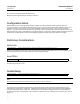
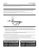
D Driver Rod Length— Enter the displacer rod length. The displacer rod length depends upon the sensor type. For a
249 sensor, obtain the displacer rod length from table 4‐1 or from the Field Communicator Help. Refer to figure 4‐2
to physically measure this value.
Torque Tube
Follow the prompts on the Field Communicator to enter torque tube data.
D Torque Rate— Displays the torque rate currently stored in the instrument.
Change Torque Rate— Permits changing the torque rate stored in the instrument.
D TT Material— Displays the torque tube material currently stored in the instrument.
Note
A sensor with an N05500 torque tube may have NiCu on the nameplate as the torque tube material.
TT Comp Selection— Torque Tube Compensation Selection permits changing the torque tube material stored in the
instrument.
D TT Comp Table— Torque Tube Compensation Table permits you to load a table with the material temperature
coefficients.
Instrument Mounting
Follow the prompts on the Field Communicator display to specify if the instrument is to the right or left of the
displacer. See figure 2‐5.
Sensor Damping
Follow the prompts on the Field Communicator display to configure the input filter.
Time constant for the input filter, in seconds, for the A/D measurement. The filter is applied before PV processing,
after the A/D conversion. Range is 0 to 16 seconds in 0.1 second increments. The default value is 0.0 seconds. To
disable the filter, set the time constant to 0 seconds. This filter is provided for extreme input noise situations. Use of
this filter normally should not be necessary.
Net instrument response is a combination of analog input filtering and output filtering.