Quick Start Guide DLC3010 Digital Level Controller D103214X012 September 2014 Fisherr FIELDVUE™ DLC3010 Digital Level Controller Contents Installation . . . . . . . . . . . . . . . . . . . . . 3 Mounting . . . . . . . . . . . . . . . . . . . . . . . 9 Electrical Connections . . . . . . . . . . . 13 Initial Setup . . . . . . . . . . . . . . . . . . . . 21 Calibration . . . . . . . . . . . . . . . . . . . . . 27 Schematics . . . . . . . . . . . . . . . . . . . . 32 Specifications . . . . . . . . . . . . .
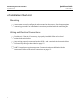
DLC3010 Digital Level Controller Quick Start Guide September 2014 D103214X012 nInstallation Check List Mounting j Instrument correctly configured and mounted on the sensor. See the appropriate mounting procedure or installation instructions provided with the mounting kit. Wiring and Electrical Connections 2 j Conduit or I.S. barrier, if necessary, is properly installed. Refer to local and national electrical codes.
Quick Start Guide D103214X012 DLC3010 Digital Level Controller September 2014 Installation WARNING To avoid personal injury, always wear protective gloves, clothing, and eyewear when performing any installation operations. Personal injury or property damage due to sudden release of pressure, contact with hazardous fluid, fire, or explosion can be caused by puncturing, heating, or repairing a displacer that is retaining process pressure or fluid.
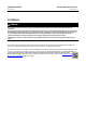
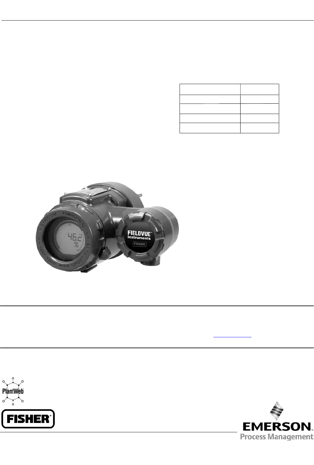
Quick Start Guide DLC3010 Digital Level Controller D103214X012 September 2014 Figure 1.
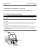
Quick Start Guide DLC3010 Digital Level Controller D103214X012 September 2014 Configuration: On the Bench or in the Loop Configure the digital level controller before or after installation. It may be useful to configure the instrument on the bench before installation to ensure proper operation, and to familiarize yourself with its functionality. Protecting the Coupling and Flexures CAUTION Damage to flexures and other parts can cause measurement errors.
DLC3010 Digital Level Controller September 2014 Quick Start Guide D103214X012 CAUTION When shipping an instrument mounted on a sensor, if the lever assembly is coupled to the linkage, and the linkage is constrained by the displacer blocks, use of the lever lock may result in damage to bellows joints or flexure. 2.
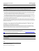
Quick Start Guide DLC3010 Digital Level Controller D103214X012 September 2014 Table 1. Hazardous Area Classifications—CSA (Canada) Certification Body Certification Obtained Ex ia Intrinsically Safe Class I,II,III Division 1 GP A,B,C,D, E,F,G T6 per drawing 28B5744 (see figure 14) CSA Entity Rating Vmax = 30 VDC Imax = 226 mA Ci = 5.5 nF Li = 0.
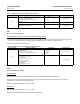
Quick Start Guide DLC3010 Digital Level Controller D103214X012 September 2014 Type n This equipment shall be used with a cable entry ensuring an IP66 minimum and being in compliance with the relevant European standards. Operating ambient temperature: -40_C to + 80_C Refer to table 3 for additional approval information. Table 3.
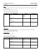
Quick Start Guide DLC3010 Digital Level Controller D103214X012 September 2014 Mounting Mounting the 249 Sensor The 249 sensor is mounted using one of two methods, depending on the specific type of sensor. If the sensor has a caged displacer, it typically mounts on the side of the vessel as shown in figure 3. If the sensor has a cageless displacer, the sensor mounts on the side or top of the vessel as shown in figure 4. Figure 3. Typical Caged Sensor Mounting Figure 4.
DLC3010 Digital Level Controller Quick Start Guide September 2014 D103214X012 DLC3010 Orientation Mount the digital level controller with the torque tube shaft clamp access hole (see figure 2) pointing downward to allow accumulated moisture drainage. Note If alternate drainage is provided by the user, and a small performance loss is acceptable, the instrument can be mounted in 90 degree rotational increments around the pilot shaft axis.
Quick Start Guide DLC3010 Digital Level Controller D103214X012 September 2014 Figure 5. Typical Mounting Positions for FIELDVUE DLC3010 Digital Level Controller on Fisher 249 Sensor SENSOR LEFT‐OF‐DISPLACER 1 5 RIGHT‐OF‐DISPLACER 7 3 6 8 1 CAGED 4 2 1 4 3 1 5 2 8 6 7 CAGELESS 1 NOT AVAILABLE FOR SIZE NPS 2 CL300 AND CL600 249C SENSOR. 19B2787 Rev. D 19B6600 Rev. C B1407‐2 Figure 6. Close‐up of Set‐Screw SET‐SCREW 4.
Quick Start Guide DLC3010 Digital Level Controller D103214X012 September 2014 Mounting the Digital Level Controller for Extreme Temperature Applications Refer to figure 7 for parts identification except where otherwise indicated. The digital level controller requires an insulator assembly when temperatures exceed the limits shown in figure 8. A torque tube shaft extension is required for a 249 sensor when using an insulator assembly. Figure 7.
Quick Start Guide DLC3010 Digital Level Controller D103214X012 September 2014 1. For mounting a digital level controller on a 249 sensor, secure the shaft extension to the sensor torque tube shaft via the shaft coupling and set screws, with the coupling centered as shown in figure 7. 2. Slide the access handle to the locked position to expose the access hole. Press on the back of the handle as shown in figure 2 then slide the handle toward the front of the unit.
Quick Start Guide DLC3010 Digital Level Controller D103214X012 September 2014 Figure 9. Connecting a Field Communicator to the Digital Level Controller Loop 230 RL 1100 1 + − + Reference meter + for calibration or monitoring operation. May be a voltmeter − across 250 ohm resistor or a current meter. + A HART‐based communicator may be connected at any termination point in the signal loop. Signal loop must have between 250 and 1100 ohms load for communication.
Quick Start Guide DLC3010 Digital Level Controller D103214X012 September 2014 Field Wiring WARNING To avoid personal injury or property damage caused by fire or explosion, remove power to the instrument before removing the digital level controller cover in an area which contains a potentially explosive atmosphere or has been classified as hazardous. Note For intrinsically safe applications, refer to the instructions supplied by the barrier manufacturer.
DLC3010 Digital Level Controller September 2014 Quick Start Guide D103214X012 Grounding WARNING Personal injury or property damage can result from fire or explosion caused by the discharge of static electricity when flammable or hazardous gases are present. Connect a 14 AWG (2.1 mm2) ground strap between the digital level controller and earth ground when flammable or hazardous gases are present. Refer to national and local codes and standards for grounding requirements.
Quick Start Guide D103214X012 DLC3010 Digital Level Controller September 2014 Communication Connections WARNING Personal injury or property damage caused by fire or explosion may occur if this connection is attempted in an area which contains a potentially explosive atmosphere or has been classified as hazardous. Confirm that area classification and atmosphere conditions permit the safe removal of the terminal box cap before proceeding.
DLC3010 Digital Level Controller September 2014 Quick Start Guide D103214X012 the instrument drives its output to either below 3.70 mA or above 22.5 mA, depending on the position (HI/LO) of the alarm jumper. An alarm condition occurs when the digital level controller self‐diagnostics detect an error that would render the process variable measurement inaccurate, incorrect, or undefined, or a user defined threshold is violated.
Quick Start Guide DLC3010 Digital Level Controller D103214X012 September 2014 Loop Test (optional) Field Communicator Service Tools > Maintenance > Tests > Loop Test (3-3-1-1) or (3-3-1-2) if LCD Configuration is installed Loop test can be used to verify the controller output, the integrity of the loop, and the operations of any recorders or similar devices installed in the loop. To initiate a loop test, perform the following procedure: 1. Connect a reference meter to the controller.
DLC3010 Digital Level Controller Quick Start Guide D103214X012 September 2014 nConfiguration and Calibration Check List j Initial setup complete. Perform the Instrument Setup procedure, using Guided Setup, on page 22. j Calibration complete. Perform the Guided Calibration procedure on page 27. j Transmitter correctly respond to an input change and is stable. Refer to the Troubleshooting section of the FIELDVUE DLC3010 Digital Level Controller Instruction Manual (D102748X012).
Quick Start Guide DLC3010 Digital Level Controller D103214X012 September 2014 Configuration and Calibration Initial Setup If a DLC3010 digital level controller ships from the factory mounted on a 249 sensor, initial setup and calibration is not necessary. The factory enters the sensor data, couples the instrument to the sensor, and calibrates the instrument and sensor combination.
DLC3010 Digital Level Controller Quick Start Guide D103214X012 September 2014 D Instrument mounting (right or left of displacer) D Measurement Application (level, interface, or density) Configuration Advice Guided Setup directs you through initialization of configuration data needed for proper operation. When the instrument comes out of the box, the default dimensions are set for the most common Fisher 249 construction, so if any data is unknown, it is generally safe to accept the defaults.
Quick Start Guide DLC3010 Digital Level Controller D103214X012 September 2014 Figure 12. Example Sensor Nameplate SENSOR TYPE DISPLACER PRESSURE RATING ASSEMBLY PRESSURE RATING DISPLACER WEIGHT 76543210 249B PSI 285/100 F 1500 PSI 2 x 32 INCHES WCB STL 103 CU‐IN 4 3/4 LBS MONEL 316 SST K MONEL/STD DISPLACER MATERIAL TRIM MATERIAL DISPLACER VOLUME 23A1725‐E sht 1 E0366 ASSEMBLY MATERIAL TORQUE TUBE MATERIAL DISPLACER SIZE (DIAMETER X LENGTH) Table 5.
Quick Start Guide DLC3010 Digital Level Controller D103214X012 September 2014 Figure 13. Method of Determining Moment Arm from External Measurements VESSEL VERTICAL CL OF DISPLACER E0283 MOMENT ARM LENGTH HORIZONTAL CL OF TORQUE TUBE 4. Select the measurement application (level, interface, or density). Note For interface applications, if the 249 is not installed on a vessel, or if the cage can be isolated, calibrate the instrument with weights, water, or other standard test fluid, in level mode.
Quick Start Guide DLC3010 Digital Level Controller D103214X012 September 2014 8.
DLC3010 Digital Level Controller September 2014 Quick Start Guide D103214X012 Coupling If the digital level controller is not already coupled to the sensor, perform the following procedure to couple the digital level controller to the sensor. 1. Slide the access handle to the locked position to expose the access hole. Press on the back of the handle, as shown in figure 2, then slide the handle toward the front of the unit. Be sure the locking handle drops into the detent. 2.
Quick Start Guide DLC3010 Digital Level Controller D103214X012 September 2014 Calibration Guided Calibration Field Communicator Configure > Calibration > Primary > Guided Calibration (2-5-1-1) Guided Calibration recommends an appropriate calibration procedures for use in the field or on the bench based on your input. Follow the Field Communicator prompts to calibrate the digital level controller.
DLC3010 Digital Level Controller September 2014 Quick Start Guide D103214X012 until sufficient buoyancy has developed to allow the linkage to move. In that case, use the calibration procedure for overweight displacers below. After the initial calibration: For a level application— Go to the Sensor Compensation menu and use 'Enter constant SG' to configure the instrument for the target process fluid density.
Quick Start Guide DLC3010 Digital Level Controller D103214X012 September 2014 The calibration process flows as follows: D Change the PV mode to Level. D Set the Level Offset to zero. D Set the Range Values to: LRV = 0.0, URV = displacer length. D Capture Zero at the lowest process condition (that is, with the displacer completely submerged in the fluid of the lowest density NOT dry). D Set Specific Gravity to the difference between the SGs of the two fluids (for example, if SG_upper = 0.
DLC3010 Digital Level Controller Quick Start Guide September 2014 D103214X012 Density Applications - with Standard Displacer and Torque Tube Note When you change 'PV is' from level or interface to density, the range values will be initialized to 0.1 and 1.0 SGU. You may edit the range values according to the specify gravity unit. It is necessary to back out of Manual Setup and reenter the Manual Setup menu to see the changes being refreshed.
Quick Start Guide D103214X012 DLC3010 Digital Level Controller September 2014 1. Determine all the information you can about the 249 hardware: 249 type, mounting sense (controller to the right or left of displacer), torque tube material and wall thickness, displacer volume, weight, length, and driver rod length. (the driver rod length is not the suspension rod length, but the horizontal distance between the centerline of the displacer and the centerline of the torque tube).
Quick Start Guide DLC3010 Digital Level Controller D103214X012 September 2014 Schematics This section includes loop schematics required for wiring of intrinsically safe installations. If you have any questions, contact your Emerson Process Management sales office. Figure 14. CSA Loop Schematic CSA ENTITY INSTALLATION DRAWING HAZARDOUS LOCATION CLASS I, GROUPS A,B,C,D CLASS II, GROUPS E,F,G CLASS III NON-HAZARDOUS LOCATION CSA CERTIFIED BARRIER FISHER TYPE DLC3010 Vmax = 30 VDC Imax = 226 mA Ci - 5.
Quick Start Guide DLC3010 Digital Level Controller D103214X012 September 2014 Figure 15. FM Loop Schematic HAZARDOUS LOCATION NON-HAZARDOUS LOCATION I.S. CLASS I,II,III DIV 1, GROUPS A,B,C,D,E,F,G N.I. CLASS I, DIV 2, GROUPS A,B,C,D FISHER TYPE DLC3010 FM APPROVED BARRIER Vmax = 30 VDC Imax = 226 mA Ci - 5.5 nF Li = 0.4 mH Pi = 1.4 W 1. THE INSTALLATION MUST BE IN ACCORDANCE WITH THE NATIONAL ELECTRIC CODE (NEC), NFPA 70, ARTICLE 504 AND ANSI/ISA RP12.6. SEE NOTE 7 2.
DLC3010 Digital Level Controller September 2014 Quick Start Guide D103214X012 Specifications Specifications for DLC3010 digital level controllers are shown in table 6. Specifications for 249 sensors are shown in table 8.
Quick Start Guide DLC3010 Digital Level Controller D103214X012 September 2014 Table 6. DLC3010 Digital Level Controller Specifications Performance Available Configurations Mounts on caged and cageless 249 sensors. See tables 11 and 12 and sensor description. Function: Transmitter Communications Protocol: HART Input Signal Level, Interface, or Density: Rotary motion of torque tube shaft proportional to changes in liquid level, interface level, or density that change the buoyancy of a displacer.
Quick Start Guide DLC3010 Digital Level Controller D103214X012 September 2014 Table 6. DLC3010 Digital Level Controller Specifications (continued) LCD Meter Indications Electromagnetic Compatibility LCD meter indicates analog output on a percent scale bar graph. The meter also can be configured to display: Meets EN 61326‐1 and EN 61326‐2‐3 Immunity—Industrial locations per Table 2 of EN 61326‐1 and Table AA.2 of EN 61326‐2‐3. Performance is shown in table 7 below.
Quick Start Guide DLC3010 Digital Level Controller D103214X012 September 2014 Table 6. DLC3010 Digital Level Controller Specifications (continued) Minimum Differential Specific Gravity With a nominal 4.4 degrees torque tube shaft rotation for a 0 to 100 percent change in liquid level (specific gravity=1), the digital level controller can be adjusted to provide full output for an input range of 5% of nominal input span. This equates to a minimum differential specific gravity of 0.
Quick Start Guide DLC3010 Digital Level Controller D103214X012 September 2014 Table 7.
Quick Start Guide DLC3010 Digital Level Controller D103214X012 September 2014 Figure 16. Theoretical Reversible Temperature Effect on Common Torque Tube Materials TORQUE RATE REDUCTION (NORMALIZED MODULUS OF RIGIDITY) 1.00 0.98 1 0.96 0.94 N05500 N06600 Gnorm 0.92 0.90 N10276 0.88 0.86 0.84 0.82 S31600 0.80 20 40 60 80 100 120 140 160 180 200 220 240 260 280 300 320 340 360 380 400 420 TEMPERATURE (_C) TORQUE RATE REDUCTION (NORMALIZED MODULUS OF RIGIDITY) 1.00 0.98 1 0.96 0.94 Gnorm 0.
Quick Start Guide DLC3010 Digital Level Controller D103214X012 September 2014 Table 8.
Quick Start Guide DLC3010 Digital Level Controller D103214X012 September 2014 Table 11.
Quick Start Guide DLC3010 Digital Level Controller D103214X012 September 2014 Figure 17.
Quick Start Guide DLC3010 Digital Level Controller D103214X012 September 2014 D Bolt Torque Information - Supplement to 249 Sensor Instruction Manuals (D103220X012) D Technical Monograph 7: The Dynamics of Level and Pressure Control D Technical Monograph 18: Level‐Trol Density Transmitter D Technical Monograph 26: Guidelines for Selection of Liquid Level Control Equipment Educational Services For information on available courses for the DLC3010 digital level controller, as well as a variety of other pr
DLC3010 Digital Level Controller September 2014 Quick Start Guide D103214X012 Neither Emerson, Emerson Process Management, nor any of their affiliated entities assumes responsibility for the selection, use or maintenance of any product. Responsibility for proper selection, use, and maintenance of any product remains solely with the purchaser and end user. Fisher and FIELDVUE are marks owned by one of the companies in the Emerson Process Management business unit of Emerson Electric Co.