
Quick Start Guide


Quick Start Guide
D103214X012
DLC3010 Digital Level Controller
September 2014
15
Field Wiring
WARNING
To avoid personal injury or property damage caused by fire or explosion, remove power to the instrument before removing
the digital level controller cover in an area which contains a potentially explosive atmosphere or has been classified as
hazardous.
Note
For intrinsically safe applications, refer to the instructions supplied by the barrier manufacturer.
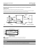
All power to the digital level controller is supplied over the signal wiring. Signal wiring need not be shielded, but use
twisted pairs for best results. Do not run unshielded signal wiring in conduit or open trays with power wiring, or near
heavy electrical equipment. If the digital controller is in an explosive atmosphere, do not remove the digital level
controller covers when the circuit is alive, unless in an intrinsically safe installation. Avoid contact with leads and
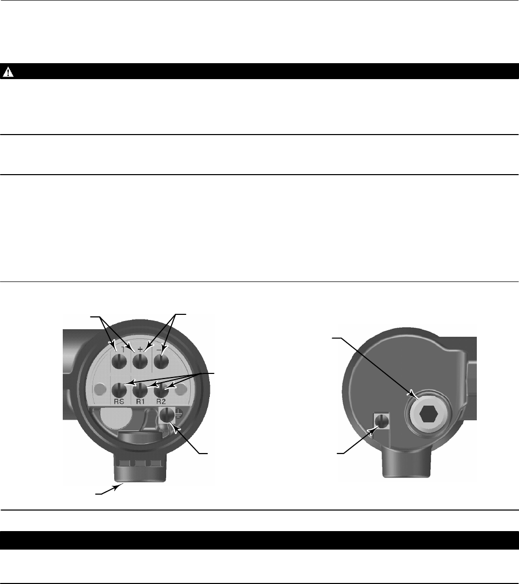
terminals. To power the digital level controller, connect the positive power lead to the + terminal and the negative
power lead to the - terminal as shown in figure 11.
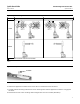
Figure 11. Digital Level Controller Terminal Box
4‐20 mA LOOP
CONNECTIONS
TEST CONNECTIONS
INTERNAL
GROUND
CONNECTION
1/2 NPT
CONDUIT
CONNECTION
FRONT VIEW
REAR VIEW
RTD
CONNECTIONS
W8041
EXTERNAL
GROUND
CONNECTION
1/2 NPT
CONDUIT
CONNECTION
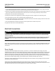
CAUTION
Do not apply loop power across the T and + terminals. This can destroy the 1 Ohm sense resistor in the terminal box. Do not
apply loop power across the Rs and - terminals. This can destroy the 50 Ohm sense resistor in the electronics module.
When wiring to screw terminals, the use of crimped lugs is recommended. Tighten the terminal screws to ensure that
good contact is made. No additional power wiring is required. All digital level controller covers must be fully engaged
to meet explosion proof requirements. For ATEX approved units, the terminal box cover set screw must engage one of
the recesses in the terminal box beneath the terminal box cover.