
Instruction Manual


Instruction Manual
D100401X012
EZ Valve
June 2014
12
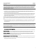
Table 3. Recommended Torque for Packing Flange Nuts (Not for Spring-Loaded Packing)
VALVE STEM DIAMETER
PRESSURE
RATING
GRAPHITE TYPE PACKING
PTFE TYPE
PACKING
Minimum Torque Maximum Torque Minimum Torque Maximum Torque
mm Inches NSm LbfSin NSm LbfSin NSm LbfS in NSm LbfSin
9.5 3/8
CL125,
CL150
3 27 5 40 1 13 2 19
CL250
CL300
4 36 6 53 2 17 3 26
CL600 6 49 8 73 3 23 4 35
12.7 1/2
CL125,
CL150
5 44 8 66 2 21 4 31
CL250
CL300
7 59 10 88 3 28 5 42
CL600 9 81 14 122 4 39 7 58
19.1 3/4
CL125,
CL150
11 99 17 149 5 47 8 70
CL250
CL300
15 133 23 199 7 64 11 95
CL600 21 182 31 274 10 87 15 131
Trim Maintenance
WARNING
Observe the warning at the start of the Maintenance section.
This procedure describes how the valve trim can be completely disassembled. When inspection or repairs are required,
perform only those steps n ecessary to accomplish the task.
Disassembly
Except where indicated, key numbers referenced in the following steps are found in figure 12.
1. Remove the actuator and the bonnet according to steps 1 through 6 of the Replacing Packing procedure of the
Maintenance section.
WARNING
Avoid personal injury or property damage from valve or packing leakage.
Any damage to the gasket sealing surfaces could cause the valve to leak.
The surface finish of the valve stem (key 7) is critical for making a good packing seal. The inside surface of the seat ring
retainer is critical for smooth operation of the valve plug.
The seating surfaces of the valve plug and seat ring (keys 2 and 9) are critical for proper shutoff.
Protect these parts accordingly while disassembling the trim. Gasket selection criteria is provided on page 38 of this
instruction manual.
2. Packing parts can be removed if desired. Replace these parts as described in the Replacing Packing procedure.
Valves with Plain or Extension Bonnets
Perform the following steps to remove t he valve trim.