
Data Sheet


Cavitrol III Trims
D100196X012
Product Bulletin
80.2:030
March 2012
2
Specifications
Available Valves
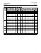
One-stage: See table 1
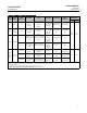
Two- and three-stage Cavitrol III: See table 3
Two- and three-stage Characterized Cavitrol III:
Consult your Emerson Process Management sales
office
End Connection Styles
Refer to appropriate valve bulletin
Shutoff Classification
Class IV (standard for one-stage trim only): [0.01% of
valve capacity at full travel tested with air at 3.4 bar
(50 psid)] per ANSI/FCI 70-2 and IEC 60534-4
Class V (standard for two- and three-stage trims,
optional for one-stage trim): [5x10
-12
m
3
/sec/bar/mm
of port diameter (0.0005 mL/min/psid/in) of water at
service pressure drop] per ANSI/FCI 70-2 and IEC
60534-4
TSO (Tight Shutoff Trim) (optional for one-, two-, and
three-stage trims): Valves with TSO trim are factory
tested to a more stringent Emerson test requirement
ofnoleakageattimeofshipmentusingANSI/FCI
Class V procedures. Consult your Emerson Process
Management sales office for additional i nformation.
Seefigure5
Maximum Inlet Pressures
(1)
Consistent with applicable ASME B16.34
pressure/temperature ratings as shown in tables 1
and 3 up to 232_C(450_F)
Maximum Pressure Drop
(1)
One-stage: 99.3 bar (1440 psi) but do not exceed the
maximum pressure and temperature for the class
rating of the valve body material used
Two-stage: 149 bar (2160 psi), but do not exceed
maximum allowable inlet pressure
Three-stage: 207 bar (3000 psi), but do not exceed
maximum allowable inlet pressure
Pressure drops are valve size and trim stage
dependent. For additional Cavitrol trim application
guidelines, contact your Emerson Process
Management sales office.
Construction Materials
See table 5
Temperature Capabilities
(1)
One-stage: -29 to 232_C(-20to450_F)
Two- and three-stage: See table 5 and figure 7
Flow Characteristic
Standard Cage: Linear
Characterized Cage: Consult your Emerson Process
Management sales office
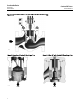
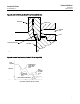
Flow Direction
Flow down (in through cage openings and out
through seat ring as shown in figure 2)
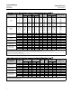
Flow Coefficients
(2)
Values given in tables 2 and 3; also see Fisher
Catalog 12
Valve Recovery Coefficients
(2)
F
L
of One-Stage Cage: See table 2
F
L
of Two-Stage Cage: 0.98
F
L
of Three-Stage Cage: 0.99
Thesevaluesdefinethemaximumallowablepressure
drop that is effective in producing flow as shown in
the following equation:
nP
allowable
=F
L
[P
1(flowing)
-r
c
P
v
]
Where
nP
allowable
=maximum allowable pressure drop that is
effective in producing flow, bar (psi)
P
1(flowing)
=flowing inlet pressure, bar, absolute (psia)
r
c
=critical pressure ratio from Catalog 12
P
v
=vapor pressure of liquid at inlet temperature, bar,
absolute (psia)
Port Diameters and Circumferences
See tables 1 and 3
Maximum Valve Plug Travel
See tables 2 and 3
-continued-