
Data Sheet


Cavitrol III Trims
D100196X012
Product Bulletin
80.2:030
March 2012
3
Specifications (continued)
Minimum Seating Force
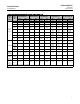
Refer to figure 4 to determine minimum seat load per
unit of port circumference; multiply that value by the
port circumference from table 1 or Catalog 14
Valve Plug Stem and Yoke Boss Diameters
Seetables1,6,and7andfigure8
Valve Plug Unbalance Area
Seetables1,3,and4
Noise Level
Use Emerson Process Management liquid noise
prediction methods available in the Emerson Process
Management sizing program
Options
J Cage with Special Characterization or J Valve Plug
forapplicationsover232_C(450_F)
1. The pressure/temperature limits in this bulletin and any applicable standard or code limitation for valve should not be exceeded.
2. For standard linear cage. Consult your Emerson Process Management sales office for flow coefficients and valve recovery coefficients of cages with optional characteristics.
Principle of Operation
Cavitation, the formation and subsequent collapse of
vapor bubbles in liquid flow streams, is a major source
of damage in control valves and adjacent piping.
As liquid passes through a restriction in a control valve,
the liquid velocity increases, while the liquid pressure
decreases. The pressure reaches a minimum at a point
called the vena contracta, and if the pressure at this
point falls to or below the vapor pressure of the liquid
(the pressure at which the liquid vaporizes), vapor
bubbles form in the flow stream.
Downstream of the vena contracta, flow area
increases, velocity decreases, and pressure increases. If
this recovered pressure is sufficient to raise the
pressure above the liquid vapor pressure, the vapor
bubbles will collapse. The collapsing bubbles generate
significant noise and vibration, and can mechanically
attack pipe walls and valve components. This attack
can lead to the failure of conventional valve
components, particularly t he valve plug and seat ring.
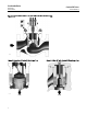
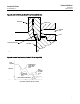
Cavitrol III One-Stage Trim
The Cavitrol III one-stage trim (figures 1 and 2) can
effectively eliminate cavitation damage in a properly
sized and selected control valve. Each cage hole is
shaped to create a small flow stream with a vena
contracta pressure higher than that typically present in
the flow stream of a standard cage. This higher vena
contracta pressure reducesthefluid'stendencyto
cavitate. Each hole in a Cavitrol III one-stage cage is
also designed to reduce fluid turbulence, and the holes
are spaced diametrically around the cage
circumference; both features dissipate fluid pressure
and help to increase capacity.
Cavitrol III one-stage trim can also be used to control
cavitation damage. When selected and sized for this
type of service, the radius edge on the valve plug and
the diametrically opposed cage holes direct the
cavitating fluid flow away from metal surfaces into the
valve body cavity void. In this manner, damage from
cavitating fluid flow is controlled.
Service conditions of each application govern whether
cavitation damage is effectively eliminated or
controlled.
Cavitrol III Two- and Three-Stage
Trims
The Cavitrol III two-and three-stage cages are
concentric cylinders (or stages) (figure 3) with
specially-shaped orifices. The choice of cage depends
on the inlet pressure and the required pressure drop. In
operation, liquid passes through the orifices in each
stage, undergoing a portion of the total required
pressure drop. This partial pressure drop in each stage
of a properly-sized valve normally prevents the liquid
pressure from falling to or below its vapor pressure,
eliminating the formation of vapor bubbles.
A characterized Cavitrol III two-or three-stage trim can
be specified on those applications where the pressure
drop across the valve decreases with increasing valve
plug travel. Characterized Cavitrol III two- or
three-stage trim c onsists of two or three stages at the
beginning of valve plug travel. Then, as the valve is
required to take less pressure drop, cage sections with
fewer stages are used.