Instruction Manual DVC6200 Digital Valve Controller D103409X012 December 2013 Fisherr FIELDVUE™ DVC6200 Digital Valve Controller This manual applies to Instrument Level HC, AD, PD, ODV Device Type 03 Device Revision 2 Hardware Revision 1 Firmware Revision 9, 10 & 11 DD Revision 8 AC 07 2 1 9, 10 & 11 1 Contents Section 1 Introduction . . . . . . . . . . . . . . . . . 3 Scope of Manual . . . . . . . . . . . . . . . . . . . . . . . . . . . . . Conventions Used in this Manual . . . . . . . . . . . . . .
Instruction Manual DVC6200 Digital Valve Controller D103409X012 December 2013 Contents (continued) Alerts . . . . . . . . . . . . . . . . . . . . . . . . . . . . . . . . . . . . . Electronics Alerts . . . . . . . . . . . . . . . . . . . . . . . Processor Impaired Alerts . . . . . . . . . . . . . . . . Sensor Alerts . . . . . . . . . . . . . . . . . . . . . . . . . . . Environmental Alerts . . . . . . . . . . . . . . . . . . . . Travel Alerts . . . . . . . . . . . . . . . . . . . . . . . . . . . .
Instruction Manual Introduction D103409X012 December 2013 Section 1 Introduction Scope of Manual This instruction manual is a supplement to the DVC6200 Series Quick Start Guide (D103556X012) that ships with every instrument.
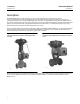
Introduction Instruction Manual December 2013 D103409X012 Description DVC6200 digital valve controllers (figures 1‐1 and 1‐2) are communicating, microprocessor‐based current‐to‐pneumatic instruments. In addition to the normal function of converting an input current signal to a pneumatic output pressure, the DVC6200 digital valve controller, using the HARTr communications protocol, gives easy access to information critical to process operation.
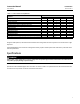
Instruction Manual Introduction D103409X012 December 2013 Table 1‐1.
Introduction Instruction Manual December 2013 D103409X012 Table 1‐2. Specifications Output Signal Available Mounting DVC6200 digital valve controller or DVC6215 feedback unit: J Integral mounting to the Fisher GX Control Valve and Actuator System J Window mounting to Fisher rotary actuators J Sliding‐stem linear applications J Quarter‐turn rotary applications Pneumatic signal, up to full supply pressure Minimum Span: 0.4 bar (6 psig) Maximum Span: 9.
Instruction Manual Introduction D103409X012 December 2013 Table 1‐2. Specifications (continued) PESO CCOE— Petroleum and Explosives Safety Organisation - Chief Controller of Explosives (India) TIIS— Technology Institution of Industrial Safety (Japan) Contact your Emerson Process Management sales office for classification/certification specific information. Vibration Testing Method Tested per ANSI/ISA-S75.13.01 Section 5.3.5. A resonant frequency search is performed on all three axes.
Introduction Instruction Manual December 2013 D103409X012 Table 1‐2. Specifications (continued) Declaration of SEP Fisher Controls International LLC declares this product to be in compliance with Article 3 paragraph 3 of the Pressure Equipment Directive (PED) 97 / 23 / EC. It was designed and manufactured in accordance with Sound Engineering Practice (SEP) and cannot bear the CE marking related to PED compliance.
Instruction Manual Introduction D103409X012 December 2013 D HART Field Device Specification - Supplement to Fisher FIELDVUE DVC6000 and DVC6200 HW1 Digital Valve Controller Instruction Manuals (D103649X012) D Using the HART Tri‐Loop HART‐to‐Analog Signal Converter with FIELDVUE Digital Valve Controllers - Supplement to HART Communicating FIELDVUE Instrument Instruction Manuals (D103267X012) D Lock‐in‐Last Strategy - Supplement to Fisher FIELDVUE DVC6000 or DVC6200 Digital Valve Controller Instruction Ma
Introduction Instruction Manual December 2013 D103409X012 10
Instruction Manual Installation D103409X012 December 2013 Section 2 Installation22 WARNING Avoid personal injury or property damage from sudden release of process pressure or bursting of parts. Before proceeding with any Installation procedures: D Always wear protective clothing, gloves, and eyewear to prevent personal injury or property damage. D If installing into an existing application, also refer to the WARNINGS at the beginning of the Maintenance section of this instruction manual.
Installation Instruction Manual December 2013 D103409X012 The feedback system for the DVC6200 digital valve controller utilizes a magnetic assembly for linkage‐less, non‐contacting position measurement. In order to prevent inadvertent stem movement while the instrument is in operation, magnetic tools (such as a magnetic‐tipped screwdriver) should not be used. Note The magnet assembly may be referred to as a magnetic array in user interface tools.
Instruction Manual Installation D103409X012 December 2013 Figure 2‐2. Travel Range VALID TRAVEL RANGE 50 mm (2 INCH) SHOWN MAGNET ASSEMBLY (ATTACHED TO VALVE STEM) W9706 INDEX MARK Note Mounting the instrument vertically, with the vent at the bottom of the assembly, or horizontally, with the vent pointing down, is recommended to allow drainage of moisture that may be introduced via the instrument air supply.
Instruction Manual Installation D103409X012 December 2013 For general mounting guidelines, refer to the DVC6200 Series quick start guide (D103556X012), available at www.fisher.com or your Emerson Process Management sales office. Table 2‐1.
Instruction Manual Installation D103409X012 December 2013 Figure 2‐4. FIELDVUE DVC6205 Base Unit with Mounting Bracket (Rear View) 57 (2.25) 72 (2.82) 10C1796‐A 2 MOUNTING HOLES 8.6 (0.34) MM (INCH) Figure 2‐5.
Instruction Manual Installation D103409X012 December 2013 Figure 2‐6. FIELDVUE DVC6205 Base Unit Pipestand Mounting 4‐INCH 1/4‐20 HEX HEAD SCREW STANDOFF MOUNTING BRACKET X0437 Mounting the DVC6215 Feedback Unit If ordered as part of a control valve assembly, the factory mounts the feedback unit on the actuator, makes pneumatic connections to the actuator, sets up, and calibrates the instrument.
Instruction Manual Installation D103409X012 December 2013 CAUTION The magnet assembly material has been specifically chosen to provide a long‐term stable magnetic field. However, as with any magnet, care must be taken when handling the magnet assembly. Another high powered magnet placed in close proximity (less than 25 mm) can cause permanent damage. Potential sources of damaging equipment include, but are not limited to: transformers, DC motors, stacking magnet assemblies.
Installation December 2013 Instruction Manual D103409X012 There are a variety of mounting brackets and kits that are used to mount the DVC6215 to different actuators. Note The DVC6215 feedback unit uses the same mountings as the DVC6200 digital valve controller.
Instruction Manual Installation D103409X012 December 2013 CAUTION Do not install a magnet assembly that is shorter than the physical travel of the actuator. Loss of control will result from the magnet assembly moving outside the range of the index mark in the feedback slot of the DVC6215 housing. 4. Using the alignment template (supplied with the mounting kit), position the magnet assembly inside the retaining slot. 5. Align the magnet assembly as follows: For air‐to‐open actuators (e.g.
Instruction Manual Installation D103409X012 December 2013 7. Mount the feedback unit to the mounting bracket, using the mounting bolts. 8. Check for clearance between the magnet assembly and the DVC6215 feedback slot. Note Ensure that there is clearance between the magnet assembly and the DVC6215 housing slot throughout the full range of travel. Fisher Rotary Actuators and Sliding‐Stem Linear Actuators over 210 mm (8.
Instruction Manual Installation D103409X012 December 2013 2. Verify that the appropriate cam is installed on the actuator as described in the instructions included with the mounting kit. 3. Mount the DVC6215 on the actuator as follows: D If required, a mounting adaptor is included in the mounting kit. Attach the adaptor to the feedback unit, then attach the feedback unit assembly to the actuator. The roller on the feedback arm will contact the actuator cam as it is being attached.
Installation December 2013 Instruction Manual D103409X012 Sliding‐Stem Linear Actuators over 210 mm (8.25 Inches) Travel Refer to the following guidelines when mounting on sliding‐stem linear actuators over 210 mm (8.25 inches) travel (see figure 2‐13). 1. Isolate the control valve from the process line pressure and release pressure from both sides of the valve body. Shut off all pressure lines to the pneumatic actuator, releasing all pressure from the actuator.
Instruction Manual Installation D103409X012 December 2013 Figure 2‐15. Air‐to‐Open Fisher GX Magnet Assembly Alignment Figure 2‐16. Air‐to‐Close Fisher GX Magnet Assembly Alignment ALIGNMENT TEMPLATE RETAINING SLOT INDEX MARK ALIGNMENT TEMPLATE RETAINING SLOT INDEX MARK W9218 W9219 5. Tighten the fasteners and remove the alignment template. Continue on with the appropriate step 6 below. Note Use a flat end hex key to tighten the mounting assembly fasteners to a torque of 2.
Instruction Manual Installation D103409X012 December 2013 Figure 2‐17. Modifications for Fisher GX Actuator; Air‐to‐Open Construction Only PNEUMATIC TUBING FROM THE DVC6205 PNEUMATIC PORT INSTALL O‐RING X0128 Air‐to‐Close GX Actuators 6. Using a 5 mm hex wrench, attach the feedback unit to the GX actuator mounting pad. 7. Check for clearance between the magnet assembly and the DVC6215 feedback slot. 8. Install tubing between the actuator casing and the appropriate DVC6215 pneumatic output port. 9.
Instruction Manual Installation D103409X012 December 2013 Quarter‐Turn Rotary Actuators The DVC6215 feedback unit can be mounted to any quarter‐turn rotary actuator, as well as those that comply with the NAMUR guidelines. A mounting bracket and associated hardware are required. Refer to figure 2‐18. 1. Isolate the control valve from the process line pressure and release pressure from both sides of the valve body. Shut off all pressure lines to the actuator, releasing all pressure from the actuator.
Instruction Manual Installation D103409X012 December 2013 Mounting Fisher 67CFR Filter Regulator A 67CFR filter regulator, when used with a DVC6200 digital valve controller, can be mounted one of three ways. Integral‐Mounted Regulator Refer to figure 2‐20. Lubricate an O‐ring and insert it in the recess around the SUPPLY connection on the digital valve controller. Attach the 67CFR filter regulator to the side of the digital valve controller.
Instruction Manual Installation D103409X012 December 2013 Figure 2‐21. Pressure Connections LOOP CONNECTIONS TERMINAL BOX OUTPUT A CONNECTION 1/2 NPT WIRING TERMINAL BOX X0379 FEEDBACK CONNECTIONS TERMINAL BOX W9615 DVC6205 BASE UNIT OUTPUT B CONNECTION SUPPLY CONNECTION VALVE MOUNTED UNIT Supply WARNING To avoid personal injury or property damage resulting from bursting of parts, do not exceed maximum supply pressure.
Installation December 2013 Instruction Manual D103409X012 D Ensure that the cover is correctly installed before putting this unit back into service. Failure to do so could result in personal injury or property damage from fire or explosion. The DVC6200 can be used with air or natural gas as the supply medium. If using natural gas as the pneumatic supply medium, natural gas will be used in the pneumatic output connections of the DVC6200 to any connected equipment.
Instruction Manual Installation D103409X012 December 2013 Double‐Acting Actuators DVC6200 digital valve controllers on double‐acting actuators always use relay A. With no input current, OUTPUT A is at 0 pressure and OUTPUT B is at full supply pressure when the relay is properly adjusted. To have the actuator stem extend from the cylinder with increasing input signal, connect OUTPUT A to the upper actuator cylinder connection. Connect OUTPUT B to the lower cylinder connection.
Installation December 2013 Instruction Manual D103409X012 Vent WARNING Personal injury or property damage can occur from cover failure due to overpressure. Ensure that the housing vent opening is open and free of debris to prevent pressure buildup under the cover. WARNING This unit vents the supply medium into the surrounding atmosphere.
Instruction Manual Installation D103409X012 December 2013 Personal injury or property damage caused by fire or explosion may occur if this connection is attempted in a potentially explosive atmosphere or in an area that has been classified as hazardous. Confirm that area classification and atmosphere conditions permit the safe removal of the terminal box cover before proceeding. The valve may move in an unexpected direction when power is applied to the DVC6200 digital valve controller.
Installation December 2013 Instruction Manual D103409X012 WARNING Personal injury or property damage, caused by fire or explosion, can result from the discharge of static electricity. Connect a 14 AWG (2.08 mm2) ground strap between the digital valve controller and earth ground when flammable or hazardous gases are present. Refer to national and local codes and standards for grounding requirements. 4.
Instruction Manual Installation D103409X012 December 2013 Figure 2‐25.
Instruction Manual Installation D103409X012 December 2013 CAUTION Failure to secure the cable wires in the support clips in step 9 can result in broken wires in applications with high levels of vibration. 9. Secure the cable wires, using the support clips in the DVC6215 feedback unit (as shown in figure 2‐26), to help prevent shifting and movement of the wires. 10. Replace and hand‐tighten all covers. Figure 2‐26.
Instruction Manual Installation D103409X012 December 2013 Figure 2‐27. HART Filter Application NON‐HART BASED DCS I/O I/O HART FILTER 4‐20 mA + HART DIGITAL VALVE CONTROLLER Tx Tx VALVE A6188‐1 Voltage Available The voltage available at the DVC6200 digital valve controller must be at least 11 volts DC. The voltage available at the instrument is not the actual voltage measured at the instrument when the instrument is connected.
Instruction Manual Installation D103409X012 December 2013 Figure 2‐28. Determining Voltage Available at the Instrument TOTAL LOOP CABLE RESISTANCE COMPLIANCE VOLTAGE THUM ADAPTER (IF USED) CONTROL SYSTEM + - INTRINSIC SAFETY BARRIER (if used) HART FILTER (if used) Calculate Voltage Available at the Instrument as follows: + AVAILABLE AT THE - INSTRUMENT Example Calculation 18.5 volts (at 21.05 mA) Control system compliance voltage 1 – Filter voltage drop (if used) VOLTAGE R – 2.
Instruction Manual Installation D103409X012 December 2013 Compliance Voltage If the compliance voltage of the control system is not known, perform the following compliance voltage test. 1. Disconnect the field wiring from the control system and connect equipment as shown in figure 2‐29 to the control system terminals. Figure 2‐29. Voltage Test Schematic 1 kW POTENTIOMETER MILLIAMMETER VOLTMETER CIRCUIT UNDER TEST A6192‐1 2. Set the control system to provide maximum output current. 3.
Instruction Manual Installation D103409X012 December 2013 Length(ft) = [160,000 - 50,000pF] [50pF/ft] Length = 2200 ft. The HART communication cable length is limited by the cable characteristic capacitance. To increase cable length, select a wire with lower capacitance per foot. Contact your Emerson Process Management sales office for specific information relating to your control system.
Instruction Manual D103409X012 Installation December 2013 Commissioning the Digital Valve Controller for use with the HART Tri‐Loop Signal Converter To prepare the digital valve controller for use with a 333 HART Tri‐Loop, you must configure the digital valve controller to burst mode, and select Burst Command 3. In burst mode, the digital valve controller provides digital information to the HART Tri‐Loop HART‐to‐Analog Signal Converter.
Installation December 2013 40 Instruction Manual D103409X012
Instruction Manual Basic Setup D103409X012 December 2013 Section 3 Basic Setup33 Instrument Mode Hot Key > Instrument Mode (Hot Key‐1) Field Communicator Configure > Detailed Setup > Mode and Protection > Instrument Mode (1‐2‐1‐1) To setup and calibrate the instrument, the instrument mode must be Out Of Service. If the mode is not Out Of Service, select Out Of Service from the Instrument Mode menu and press ENTER.
Instruction Manual Basic Setup D103409X012 December 2013 Basic Setup Field Communicator Configure > Guided Setup (1‐1) WARNING Changes to the instrument setup may cause changes in the output pressure or valve travel. Depending on the application, these changes may upset process control, which may result in personal injury or property damage. Note To setup and calibrate the instrument, the protection must be None and the Instrument Mode must be Out Of Service.
Instruction Manual Basic Setup D103409X012 December 2013 Table 3‐1. Factory Default Settings Setup Parameter Default Setting Analog Input Units Analog In Range High Analog In Range Low Control Mode Restart Control Mode mA 20.0 mA 4.
Instruction Manual Basic Setup D103409X012 December 2013 If a double‐acting relay is used, you will be prompted to run the relay adjustment when auto calibration is selected. Select Yes to adjust the relay. For additional information refer to Relay Adjustment on page 83. If after completing the Setup Wizard the valve seems slightly unstable or unresponsive, you can improve operation by selecting either Performance Tuner or Stabilize/Optimize.
Instruction Manual Basic Setup D103409X012 December 2013 Stabilizing/Optimizing Valve Response Hot Key > Stabilize/Optimize (Hot Key‐4) Field Communicator Instrument level HC only Configure > Guided Setup > Stabilize/Optimize (1‐1‐2) Note Stabilize/Optimize is available for instrument level HC, AD, PD, and ODV. WARNING During Stabilize/Optimize the valve may move, causing process fluid or pressure to be released.
Basic Setup December 2013 46 Instruction Manual D103409X012
Instruction Manual Detailed Setup D103409X012 December 2013 Section 4 Detailed Setup Detailed Setup44 Field Communicator Configure > Detailed Setup (1‐2) Note Detailed Setup is available for instrument level HC, AD, PD, and ODV. Detailed Setup allows you to configure the digital valve controller to your application. Table 4‐1 lists the default settings for a standard factory configuration. You can adjust actuator response, set the various modes, alerts, ranges, travel cutoffs and limits.
Instruction Manual Detailed Setup D103409X012 December 2013 Table 4‐1. Default Detailed Setup Parameters (continued) Setup Parameter Cycle Counter Alert Enable Cycle Counter Alert Deadband Travel History Alerts Cycle Counter Alert Point Travel Accumulator Alert Enable 1% Pressure Deviation Alert Enable 5% 9.99 sec Yes 5 psi(3) Pressure Deviation Alert Time 9.
Instruction Manual Detailed Setup D103409X012 December 2013 Mode and Protection Mode Instrument Mode Hot Key > Instrument Mode (Hot Key‐1) Field Communicator Configure > Detailed Setup > Mode and Protection > Instrument Mode (1‐2‐1‐1) Instrument Mode allows you to either take the instrument Out Of Service or place it In Service.
Instruction Manual Detailed Setup D103409X012 December 2013 the instrument is in burst mode. Between each burst mode transmission sent by the instrument, a short pause allows the Field Communicator or control system to initiate a request. The instrument receives the request, processes the response message, and then continues “bursting” the burst mode data. D Burst Enable—Yes or no. Burst mode must be enabled before you can change the burst mode command.
Instruction Manual Detailed Setup D103409X012 December 2013 Two levels of protection are available: D Config & Calib—Both setup and calibration are protected. Prohibits changing calibration and protected setup parameters. D None—Neither setup nor calibration is protected. Allows changing calibration and setup parameters. Table 4‐2 lists configurable parameters in the instrument and the requirements for modifying these parameters, in terms of instrument mode and protection.
Instruction Manual Detailed Setup D103409X012 December 2013 Table 4‐2.
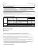
Instruction Manual Detailed Setup D103409X012 December 2013 Table 4‐3. Gain Values for Preselected Travel Tuning Sets Tuning Set Velocity Gain Minor Loop Feedback Gain C D E F G Proportional Gain 4.4 4.8 5.5 6.2 7.2 3.0 3.0 3.0 3.1 3.6 35 35 35 35 34 H I J K L M X (Expert) 8.4 9.7 11.3 13.1 15.5 18.0 User Adjusted 4.2 4.85 5.65 6.0 6.0 6.
Instruction Manual Detailed Setup D103409X012 December 2013 Table 4‐4. Actuator Information for Initial Setup Actuator Manufacturer Actuator Model 585C & 585CR 657 667 1051 & 1052 1061 Fisher Actuator Size Actuator Style 25 50 60 68, 80 100, 130 30 34, 40 45, 50 46, 60, 70, 76, & 80‐100 30 34, 40 45, 50 46, 60, 70, 76, & 80‐100 20, 30 33 40 60, 70 Piston Dbl w/ or w/o Spring. See actuator instruction manual and nameplate.
Instruction Manual Detailed Setup D103409X012 December 2013 D Performance Tuner Note The Performance Tuner is available for instrument level AD, PD, and ODV, and can only be run while in Travel control mode. The Performance Tuner is used to determine digital valve controller tuning. It can be used with digital valve controllers mounted on most sliding‐stem and rotary actuators, including Fisher and other manufacturers' products.
Instruction Manual Detailed Setup D103409X012 December 2013 In addition, you can specify Expert tuning and individually set the pressure proportional gain, pressure integrator gain, and pressure minor loop feedback gain. Individually setting or changing any tuning parameter will automatically change the tuning set to X (expert). Note Use Expert tuning only if standard tuning has not achieved the desired results.
Instruction Manual D103409X012 Detailed Setup December 2013 pressure, depending upon the zero power condition. A Travel Cutoff Low of 0.5% is recommended to help ensure maximum shutoff seat loading. When a Travel Cutoff Low is set, the Travel Limit Low is deactivated, since only one of these parameters can be active. Travel Cutoff Low is deactivated by setting it to -25%. Pressure Cutoff Lo defines the low cutoff point for the pressure in percent (%) of pre‐characterized setpoint.
Instruction Manual Detailed Setup D103409X012 December 2013 D Press Set Point—Used in conjunction with End Point Pressure Control, Pressure Set Point allows the user to select a pressure to be delivered by the instrument at the travel extreme. For a fail‐closed valve, this pressure must be sufficient to maintain the fully open position.
Instruction Manual Detailed Setup D103409X012 December 2013 Figure 4‐1.
Instruction Manual Detailed Setup D103409X012 December 2013 D Set Point Filter Time (Lag Time)—The Set Point Filter Time (Lag Time) slows the response of the digital valve controller. A value ranging from 0.2 to 10.0 can be used for noisy or fast processes to improve closed loop process control. Entering a value of 0.0 will deactivate the lag filter. In firmware 9 and 10 this parameter should be set to 0. Note Set Point Filter Time (Lag Time) is available for instrument level HC, AD, and PD.
Instruction Manual D103409X012 Detailed Setup December 2013 Zero Power Condition as per figure 4‐6. It will remain latched in that condition until power to the instrument is cycled and the failure alert has cleared. While in shutdown condition the instrument will remain powered up and able to communicate via HART. Shutdown alerts are turned off by default.
Instruction Manual Detailed Setup D103409X012 December 2013 Sensor Alerts Field Communicator Configure > Detailed Setup > Alert Setup > Sensor Alerts (1‐2‐3‐2) Travel Sensor Shutdown—When enabled, the instrument shuts down whenever there is a failure associated with the travel sensor. Temp Sensor Shutdown—When enabled, the instrument shuts down whenever there is a failure associated with the temperature sensor.
Instruction Manual Detailed Setup D103409X012 December 2013 Travel Alerts Field Communicator Configure > Detailed Setup > Alert Setup > Travel Alerts (1‐2‐3‐4) Travel—Travel displays the actual position of the valve in percent (%) of calibrated travel. Setpoint—Setpoint is the input to the characterization function. Travel Alert DB—Travel Alert Deadband is the travel, in percent (%) of ranged travel, required to clear a travel alert, once it has been set.
Detailed Setup December 2013 Instruction Manual D103409X012 D Travel Alert Hi Hi Point—The value of the travel, in percent (%) of ranged travel, which, when exceeded, sets the Travel Alert Hi Hi alert. D Travel Alert Lo Lo Point— The value of the travel, in percent (%) of ranged travel, which, when exceeded, sets the Travel Alert Lo Lo alert. Travel Limit Hi/Lo Alerts—Travel Alert Hi is set if the ranged travel rises above the alert high point.
Instruction Manual Detailed Setup D103409X012 December 2013 D Travel Limit Lo—Defines the low limit for the travel in percent (%) of ranged travel. It is the minimum allowable travel (in percent of ranged travel) for the valve. During operation, the travel target will not exceed this limit. When a Travel Limit Low is set, the Travel Cutoff Low is deactivated, since only one of these parameters can be active. Travel Limit Low is deactivated by setting it to -25.0%.
Instruction Manual Detailed Setup D103409X012 December 2013 Travel Accumulator D Travel Accumulator Alert Enable—Yes or No. Activates checking of the difference between the Travel Accumulator value and the Travel Accumulator Alert Point. The Travel Accumulation Alert is set when the Travel Accumulator value exceeds the Travel Accumulator Alert Point. It is cleared after you reset the Travel Accumulation to a value less than the alert point. Factory default is No.
Instruction Manual Detailed Setup D103409X012 December 2013 Alert Record HC, AD and PD Configure > Detailed Setup > Alert Setup > Alert Record (1‐2‐3‐6) Field Communicator ODV Configure > Detailed Setup > Alert Setup > Alert Record (1‐2‐3‐7) To be recorded, an alert must both be enabled for reporting, and the group in which it resides must be enabled for recording. Table 4‐7 lists the alerts included in each of the groups.
Instruction Manual Detailed Setup D103409X012 December 2013 Status Field Communicator Configure > Detailed Setup > Status (1‐2‐4) Follow the prompts on the Field Communicator display to configure the following parameters: Instrument Time, Calibration and Diagnostics, Operational, and Integrator. Instrument Time D Inst Time Invalid Enable—Yes or No. When enabled indicates if the Instrument Time Invalid alert is active. Factory default is Yes.
Instruction Manual Detailed Setup D103409X012 December 2013 Instrument Field Communicator Configure > Detailed Setup > Instrument (1‐2‐5) Follow the prompts on the Field Communicator display to configure the following Instrument parameters: General, Units, Analog Input Range, Relay Type, Zero Power Condition, Maximum Supply Pressure, Auxiliary Terminal Mode, Instrument Date and Time, and Calibration Status and Type. General D HART Tag—Enter an up to 8 character HART tag for the instrument.
Instruction Manual Detailed Setup D103409X012 December 2013 Figure 4‐5. Calibrated Travel to Analog Input Relationship TRAVEL RANGE HIGH ZPC = OPEN CALIBRATED TRAVEL, % ZPC = CLOSED THE SHAPE OF THESE LINES DEPENDS ON THE INPUT CHARACTERISTICS LINEAR CHARACTERISTIC SHOWN TRAVEL RANGE LOW INPUT RANGE LOW ANALOG INPUT mA OR % OF 4‐20 mA INPUT RANGE HIGH NOTE: ZPC = ZERO POWER CONDITION A6531‐1 Relay Type—There are three categories of relays that result in combinations from which to select.
Instruction Manual D103409X012 Detailed Setup December 2013 Auxiliary Terminal Action —Disabled, Alert on Open Contact, Alert on Close Contact, or Auto Travel Calibration. Selecting Alert on Open or Closed Contact activates checking the status of the auxiliary input contacts. Selecting Auto Travel Calibration permits starting an automatic travel calibration procedure by placing a jumper across the auxiliary input terminals for 3 to 5 seconds. Instrument Date and Time—Permits setting the instrument clock.
Instruction Manual Detailed Setup D103409X012 December 2013 D For instruments with Relay B: If decreasing air pressure at output B causes the magnet assembly to down, or the rotary shaft to turn clockwise, enter CW/To Bottom Inst. If it causes the magnet assembly to move up, or the rotary shaft to turn counterclockwise, enter CCW/To Top Inst. View / Edit Feedback Connection—Refer to table 4‐8 for Feedback Connection options. Choose the assembly that matches the actuator travel range.
Instruction Manual Detailed Setup D103409X012 December 2013 SIS/Partial Stroke (Instrument Level ODV) Field Communicator Configure / Setup > Detailed Setup > SIS/Partial Stroke (1‐2‐7) Note Partial Stroke is only available for instrument level ODV. Follow the prompts on the Field Communicator display to configure the following partial stroke parameters: PST Enable, and View/Edit PST Variables. PST Enable—Yes or No. Enables or disables the Partial Stroke Test.
Instruction Manual Detailed Setup D103409X012 December 2013 To set the partial stroke pressure limit manually for single acting actuators select min pressure. Select min diff press for double acting actuators. Note In order to manually set the partial stroke pressure limit with the correct value, you must be able to run a valve signature test using ValveLink software.
Instruction Manual Detailed Setup D103409X012 December 2013 Table 4‐10. Estimates for Partial Stroke Pressure Limits Actuator Style Relay Type Zero Power Condition Closed A or C Open Spring and Diaphragm Closed B Open Closed A or C Open Single Acting Piston Closed B Open Closed Double Acting Piston A Open PST Starting Point Partial Stroke Pressure Limit(1) Open Pmin - 0.25 * (Bench Set High - Bench Set Low) Closed Pmax + 0.25 * (Bench Set High - Bench Set Low) Open Pmax + 0.
Detailed Setup December 2013 76 Instruction Manual D103409X012
Instruction Manual D103409X012 Calibration December 2013 Section 5 Calibration 55 Calibration Overview When a DVC6200 digital valve controller is ordered as part of a control valve assembly, the factory mounts the digital valve controller on the actuator and connects the necessary tubing, then sets up and calibrates the controller. For digital valve controllers that are ordered separately, recalibration of the analog input or pressure sensors generally is unnecessary.
Instruction Manual Calibration D103409X012 December 2013 Travel Calibration Field Communicator Configure > Calibrate > Travel Calibration (1‐3‐1) If a double‐acting relay is used, you will be prompted to run the relay adjustment when auto or manual calibration is selected. Select Yes to adjust the relay, select No to proceed with calibration. For additional information, refer to Relay Adjustment in this section. Note Relay Adjustment is only available for the double‐acting relay (Relay A).
Instruction Manual D103409X012 Calibration December 2013 Manual Travel Calibration Two procedures are available to manually calibrate travel: D Analog Adjust D Digital Adjust Analog Calibration Adjust Connect a variable current source to the instrument LOOP + and LOOP - terminals. The current source should be capable of generating 4 to 20 mA. Follow the prompts on the Field Communicator display to calibrate the instrument's travel in percent. Note 0% Travel = Valve Closed 100% Travel = Valve Open 1.
Instruction Manual Calibration D103409X012 December 2013 2. From the adjustment menu, select the direction and size of change required to set the travel at 0%. Selecting large, medium, and small adjustments causes changes of approximately 10.0%, 1.0%, and 0.1%, respectively. If another adjustment is required, repeat step 2. Otherwise, select Done and go to step 3. 3. From the adjustment menu, select the direction and size of change required to set the travel to 100%.
Instruction Manual D103409X012 Calibration December 2013 Output Pressure Sensor To calibrate the output pressure sensor, connect an external reference gauge to the output being calibrated. The gauge should be capable of measuring maximum instrument supply pressure. Depending upon the sensor you wish to calibrate, select either Output A Sensor or Output B Sensor. Follow the prompts on the Field Communicator display to calibrate the instrument's output pressure sensor. 1.
Instruction Manual Calibration December 2013 D103409X012 1. Select a) Zero Only, or b) Zero and Span (gauge required). a. If Zero Only calibration is selected, adjust the supply pressure regulator to remove supply pressure from the instrument. Press OK. Once calibration is complete, go to step 5. b. If Zero and Span calibration is selected, adjust the supply pressure regulator to remove supply pressure from the instrument. Press OK. Adjust the supply regulator to the maximum instrument supply pressure.
Instruction Manual D103409X012 Calibration December 2013 5. Set the current source to the target value shown on the display. The target value is the Input Range High value. Press OK. 6. The following message appears: Use Increase and Decrease selections until the displayed current matches the target. Press OK when you have read this message. 7. The value of the Analog Input appears on the display. Press OK to display the adjustment menu. 8.
Instruction Manual Calibration D103409X012 December 2013 Figure 5‐1.
Instruction Manual D103409X012 Calibration December 2013 Single‐Acting Relays WARNING For Instrument Level ODV only: If the unused port is monitoring pressure, ensure that the pressure source conforms to ISA Standard 7.0.01 and does not exceed the pressure supplied to the instrument. Failure to do so could result in personal injury or property damage caused by loss of process control.
Calibration December 2013 86 Instruction Manual D103409X012
Instruction Manual Viewing Device Variables and Diagnostics D103409X012 December 2013 Section 6 Viewing Device Variables and Diagnostics66 Service Tools Note Service Tools are not available for instrument level AC. Alert Conditions Field Communicator Service Tools > Alert Conditions (2‐1) Instrument Alert Conditions, when enabled, detect many operational and performance issues that may be of interest. To view these alerts navigate to Alert Conditions.
Viewing Device Variables and Diagnostics Instruction Manual December 2013 D103409X012 Non‐Critical NVM Alert—This alert is indicated if the checksum for data, which are not critical for instrument operation, has failed. Critical NVM Alert—This alert is indicated when the Non‐Volatile Memory integrity test fails. Configuration data is stored in NVM. If this failure is indicated, restart the instrument and see if it clears. If it does not clear, replace the printed wiring board assembly.
Instruction Manual Viewing Device Variables and Diagnostics D103409X012 December 2013 Aux Terminal Alert Aux Terminal Alert—This alert is set when the auxiliary input terminals are either open or closed, depending upon the selection for the Auxiliary Input Alert State. Loop Current Validation Alert— This alert is activated if the loop current is out of valid range. If the control system is known to output currents outside of this range, the loop current shutdown should not be enabled.
Viewing Device Variables and Diagnostics Instruction Manual D103409X012 December 2013 Viewing Instrument Status Field Communicator Service Tools > Status (2‐2) Status displays the status of the Operational items listed below. The status of more than one operational item may be indicated.
Instruction Manual D103409X012 Viewing Device Variables and Diagnostics December 2013 D Ramp to Target—ramps the travel to the specified target at the rate of 1.0% per second of the ranged travel. D Step to Target—steps the travel to the specified target. Partial Stroke Test (ODV only) Field Communicator Service Tools > Partial Stroke Test (2‐5) Note Partial Stroke Test is only available for instrument level ODV.
Viewing Device Variables and Diagnostics December 2013 Instruction Manual D103409X012 Auxiliary Terminal Wiring Length Guidelines The Auxiliary Input Terminals of a DVC6200 with instrument level ODV can be used with a locally‐mounted switch for initiating a partial stroke test. Some applications require that the partial stroke test be initiated from a remote location. The length for wiring connected to the Auxiliary Input Terminals is limited by capacitance.
Instruction Manual Viewing Device Variables and Diagnostics D103409X012 December 2013 Overview Field Communicator Overview (3) The following menus are available to define and/or view information about the instrument. Note Overview is not available for instrument level AC. Analog In Analog Input shows the value of the instrument analog input in mA (milliamperes) or % (percent) of ranged input. Setpoint Setpoint shows the requested valve position in % of ranged travel post characterization.
Viewing Device Variables and Diagnostics Instruction Manual December 2013 D103409X012 D Temperature—The internal temperature of the instrument is displayed in either degrees Fahrenheit or Celsius. D Maximum Recorded Temperature—Shows the maximum temperature the instrument has experienced since installation. D Minimum Recorded Temperature—Shows the minimum temperature the instrument has experienced since installation. D Cycle Counter—Displays the number of times the valve travel has cycled.
Instruction Manual Viewing Device Variables and Diagnostics D103409X012 December 2013 D Hardware Revision—The revision number of the electrical circuitry within the instrument printed wiring board. D Instrument Level—Indicates the instrument level AC—Auto Calibrate HC—HART Communicating AD—Advanced Diagnostics PD—Performance Diagnostics ODV—Optimized Digital Valve Table 6‐2 lists the functions available for each instrument level. Table 6‐2.
Viewing Device Variables and Diagnostics December 2013 96 Instruction Manual D103409X012
Instruction Manual Maintenance and Troubleshooting D103409X012 December 2013 Section 7 Maintenance and Troubleshooting77 The DVC6200 digital valve controller enclosure is rated Type 4X and IP66, therefore periodic cleaning of internal components is not required.
Instruction Manual Maintenance and Troubleshooting D103409X012 December 2013 from fire or explosion if natural gas is used as the supply medium and appropriate preventive measures are not taken. Preventive measures may include, but are not limited to, one or more of the following: ensuring adequate ventilation and the removal of any ignition sources. D Ensure that the cover is correctly installed before putting this unit back into service.
Instruction Manual Maintenance and Troubleshooting D103409X012 December 2013 Component Replacement When replacing any of the components of the DVC6200, the maintenance should be performed in an instrument shop whenever possible. Make sure that the electrical wiring and pneumatic tubing is disconnected prior to disassembling the instrument. Removing the Module Base Refer to figure 8‐2 or 8‐4 for key number locations.
Instruction Manual Maintenance and Troubleshooting D103409X012 December 2013 5. For the DVC6205 only, disconnect the cable assembly from the LOOP connections terminal box, as shown in figure 7‐2. Figure 7‐2. FIELDVUE DVC6205 Cable Connections LOOP CONNECTIONS TERMINAL BOX CABLES FROM LOOP CONNECTIONS TERMINAL BOX PRINTED WIRING BOARD ASSEMBLY CABLES TO THE PWB FEEDBACK CONNECTIONS TERMINAL BOX Replacing the Module Base Refer to figure 8‐2 or 8‐4 for key number locations.
Instruction Manual D103409X012 Maintenance and Troubleshooting December 2013 2. Connect the two cable assemblies from the sensor board to the PWB assembly (key 50). Orientation of the connector is required. 3. For DVC6205 only, connect the cable assembly from the LOOP connections terminal box to the Feedback Connections Terminal Box (see figure 7‐2). 4. Insert the module base (key 2) into the housing (key 1). 5. Install three socket head screws (key 38) in the module base into the housing.
Instruction Manual Maintenance and Troubleshooting D103409X012 December 2013 Replacing the I/P Filter A screen in the supply port beneath the I/P converter serves as a secondary filter for the supply medium. To replace this filter, perform the following procedure: 1. Remove the I/P converter (key 41) and shroud (key 169) as described in the Removing the I/P Converter procedure. 2. Remove the screen (key 231) from the supply port. 3. Install a new screen in the supply port as shown in figure 7‐3.
Instruction Manual Maintenance and Troubleshooting D103409X012 December 2013 Figure 7‐4. I/P Converter I/P CONVERTER (KEY 41) W9328 SHROUD (KEY 169) SOCKET‐HEAD SCREWS (4) (KEY 23) BOOTS (KEY 210) 3. Install the I/P converter (key 41) straight into the module base (key 2), taking care that the two electrical leads feed into the guides in the module base. These guides route the leads to the printed wiring board assembly submodule. 4. Install the shroud (key 169) over the I/P converter (key 41). 5.
Instruction Manual Maintenance and Troubleshooting D103409X012 December 2013 2. Properly orient the PWB assembly (key 50) as you install it into the module base. The two electrical leads from the I/P converter (key 41) must guide into their receptacles in the PWB assembly and the pressure sensor bosses on the module base must fit into their receptacles in the PWB assembly. 3. Push the PWB assembly (key 50) into its cavity in the module base. 4.
Instruction Manual Maintenance and Troubleshooting D103409X012 December 2013 Pneumatic Relay Refer to figure 8‐2 or 8‐4 for key number locations. The pneumatic relay (key 24) is located on the front of the module base. Note After relay submodule replacement, calibrate the digital valve controller to maintain accuracy specifications. Removing the Pneumatic Relay 1. Loosen the four screws that attach the relay (key 24) to the module base. These screws are captive in the relay. 2. Remove the relay.
Maintenance and Troubleshooting Instruction Manual December 2013 D103409X012 Perform the following procedure to replace the gauges, tire valves, or pipe plugs. Refer to figure 8‐2 and 8‐3 for key number locations. 1. Remove the front cover (key 43). 2. Remove the gauge, pipe plug, or tire valve as follows: For gauges (key 47), the flats are on the gauge case. Use a wrench on the flats of the gauge to remove the gauge from the module base.
Instruction Manual Maintenance and Troubleshooting D103409X012 December 2013 1. Loosen the set screw (key 58) in the cap (key 4) so that the cap can be unscrewed from the terminal box. 2. After removing the cap (key 4), note the location of field wiring connections and disconnect the field wiring from the terminal box. 3. Separate the module base from the housing by performing the Removing the Module Base procedure. 4.
Instruction Manual Maintenance and Troubleshooting D103409X012 December 2013 To check the Voltage Available at the instrument, perform the following: 1. 2. 3. 4. 5. 6. 7. Connect the equipment in figure 2‐29 to the field wiring in place of the FIELDVUE instrument. Set the control system to provide maximum output current. Set the resistance of the 1 kilohm potentiometer shown in figure 2‐29 to zero. Record the current shown on the milliammeter.
Instruction Manual Maintenance and Troubleshooting D103409X012 December 2013 Table 7‐3. Instrument Troubleshooting Symptom 1. Analog input reading at instrument does not match actual current provided. Possible Cause 1a. Check the control mode using the Field Communicator. If in the Digital or Test mode, the instrument receives its set point as a digital signal. Control is not based on input current. Change Control Mode to Analog. 1b. Low control system compliance voltage. 1b.
Instruction Manual Maintenance and Troubleshooting D103409X012 December 2013 Table 7‐3. Instrument Troubleshooting (Continued) Symptom Possible Cause 3b. Restricted pneumatic passages in I/P converter. 3c. O‐ring(s) between I/P converter ass'y missing or hard and flattened losing seal. 3d. I/P converter ass'y damaged/corroded/clogged. 5. Field Communicator does not turn on. 110 3d. Check for bent flapper, open coil (continuity), contamination, staining, or dirty air supply.
Instruction Manual Maintenance and Troubleshooting D103409X012 December 2013 DVC6200 Technical Support Checklist Have the following information available prior to contacting your Emerson Process Management sales office for support. 1. Instrument serial number as read from nameplate ________________________________________________ 2.
Maintenance and Troubleshooting December 2013 112 Instruction Manual D103409X012
Instruction Manual Parts D103409X012 December 2013 Section 8 Parts88 Parts Ordering Whenever corresponding with your Emerson Process Management sales office about this equipment, always mention the controller serial number. When ordering replacement parts, refer to the 11‐character part number of each required part as found in the following parts list. Part numbers are shown for kits and recommended spares only. For part numbers not shown, contact your Emerson Process Management sales office.
Instruction Manual Parts D103409X012 December 2013 Kit Description 10* Feedback Array Kit, Aluminum Part Number Sliding Stem (Linear) [kit contains feedback array and hex socket cap screws, qty. 2, with hex key and alignment template. 210 mm (8-1/4 inch) kit also contains insert]. Stainless steel kits only for use with stainless steel mounting kits.
Instruction Manual Parts D103409X012 Key Description December 2013 Part Number Figure 8‐1.
Instruction Manual Parts D103409X012 December 2013 Key Description Part Number Key Description Part Number PWB Assembly (see figure 8‐2 and 8‐4) Pressure Gauges, Pipe Plugs, or Tire Valve Assemblies (see figure 8‐3) DVC6200 and DVC6205 DVC6200 and DVC6205 47* Pressure Gauge, nickel‐plated brass case, brass connection Double‐acting (3 req'd); Single‐acting (2 req'd) PSI/MPA Gauge Scale To 60 PSI, 0.4 MPa 18B7713X042 To 160 PSI, 1.
Instruction Manual Parts D103409X012 December 2013 Figure 8‐2.
Instruction Manual Parts D103409X012 December 2013 Figure 8‐2. FIELDVUE DVC6200 Digital Valve Controller Housing Assembly (continued) SECTION C-C SCALE 2 : 1 SECTION A-A SECTION E-E SCALE 2 : 1 SECTION F-F SCALE 2 : 1 APPLY LUBRICANT, SEALANT, OR THREAD LOCK APPLY LUBRICANT ON ALL O-RINGS UNLESS OTHERWISE SPECIFIED GE40185 sheet 2 of 3 Figure 8‐3.
Instruction Manual Parts D103409X012 December 2013 Figure 8‐4.
Instruction Manual Parts D103409X012 December 2013 Figure 8‐4.
Instruction Manual Parts D103409X012 December 2013 Figure 8‐4.
Instruction Manual Parts D103409X012 December 2013 Figure 8‐5.
Instruction Manual Principle of Operation D103409X012 December 2013 Appendix A Principle of OperationAA−A HART Communication The HART (Highway Addressable Remote Transducer) protocol gives field devices the capability of communicating instrument and process data digitally. This digital communication occurs over the same two‐wire loop that provides the 4‐20 mA process control signal, without disrupting the process signal.
Instruction Manual Principle of Operation D103409X012 December 2013 Figure A‐2. Typical FIELDVUE Instrument to Personal Computer Connections for ValveLink Software CONTROL SYSTEM HART MODEM FIELD TERM. E1362 DVC6200 digital valve controllers are loop‐powered instruments that provide a control valve position proportional to an input signal from the control room. The following describes a double‐acting digital valve controller mounted on a piston actuator.
Instruction Manual Principle of Operation D103409X012 December 2013 Figure A‐3. FIELDVUE DVC6200 Digital Valve Controller Block Diagram INPUT SIGNAL 4-20 mA + HART VALVE TRAVEL FEEDBACK PRINTED WIRING BOARD TERMINAL BOX DRIVE SIGNAL OUTPUT A AUXILIARY TERMINALS I/P CONVERTER PNEUMATIC RELAY SUPPLY PRESSURE OUTPUT B VENT VALVE AND ACTUATOR E1361 Figure A‐4.
Principle of Operation December 2013 126 Instruction Manual D103409X012
Instruction Manual Field Communicator Menu Trees D103409X012 December 2013 Appendix B Field Communicator Menu Trees This section contains the Field Communicator menu trees for instrument level HC, AD, PD, and ODV and instrument level AC. It also contains Fast Key Sequence tables with coordinates to help locate the function/variable on the appropriate menu tree.
Instruction Manual Field Communicator Menu Trees D103409X012 December 2013 Instrument Level HC, AD, PD, and ODV Function/Variable A minus B Fast‐Key Sequence Coordinates(1) Function/Variable 3‐5‐3 4‐G Device Revision 3‐D 2‐F Diagnostic Data Available Enable Diagnostic in Progress Enable 10‐H Drive Current Shutdown Drive Signal Alert Enable 10‐H Drive Signal Analog Input Analog Input Calibration Analog Input Range Hi 1‐2‐6‐4 2‐1 1‐2‐3‐6‐1 1‐2‐3‐7‐1 1‐2‐3‐6‐2 1‐2‐3‐7‐2 3‐1 1‐3‐2‐2 1‐2‐5‐3‐1
Instruction Manual Field Communicator Menu Trees D103409X012 December 2013 Fast‐Key Sequence Coordinates(1) Fast‐Key Sequence Coordinates(1) 3‐F 4‐H Status 10‐I Supply(2) Model 2‐3‐2 3‐6‐4 1‐2‐3‐6‐5‐3 1‐2‐3‐7‐5‐3 3‐7‐4 2‐2 2‐F 2‐4 3‐5‐4 1‐2‐3‐3‐2‐2 1‐2‐3‐3‐2‐1 1‐2‐3‐3‐2‐3 3‐6‐2 2‐F 4‐G 12‐D 12‐D 12‐D 4‐H 2‐H Multi‐Drop Alert Enable Non‐Critical NVM Alert Enable 1‐2‐4‐3‐2 1‐2‐3‐1‐3‐3 8‐H 12‐C Supply Pressure Lo Alert Enable(2) Supply Pressure Lo Alert Point(2) Temperature Number of Pow
Instruction Manual Field Communicator Menu Trees D103409X012 December 2013 Field Communicator Menu Tree for Instrument Level HC, AD, PD, and ODV Hot Key Burst Mode 1 Instrument Mode 2 Control Mode 3 Protection 4 Stabilize/Optimize 1‐2‐1 1‐1 1 Instrument Mode 2 Control Mode 3 Restart Control Mode 4 Burst Mode 5 Protection Guided Setup 1‐2 Detailed Setup 3 1 Guided Setup 2 Detailed Setup 3 Calibrate 2 1 Travel Calibration 1‐2‐4 1‐3‐2 3‐5 3‐7 3‐6 1 This menu is available by pressing the
Instruction Manual Field Communicator Menu Trees D103409X012 1‐2‐2‐1‐1 December 2013 Travel Tuning 1 Travel Tuning Set 2 Integral Enable 3 Integral Gain 4 Stabilize / Optimize 5 Performance Tuner A 2 1‐2‐2‐1‐2 Integral Settings 1 Integral Dead Zone 2 Integ Limit 1‐2‐2‐1‐3 B 1‐2‐3‐1‐3 1‐2‐2‐2‐2 Pressure Tuning Cutoffs and Limits 1 Pressure Tuning Set 2 Integral Enable 3 Integral Gain 3 1‐2‐2‐2‐4 End Pt Press Control 1 End Pt Control Enab 2 PST Start Pt 3 Press Set Pt 4 Press Sat Time 1‐2‐3‐1
Instruction Manual Field Communicator Menu Trees D103409X012 December 2013 Instrument Level AC Fast‐Key Sequence Coordinates(1) 1‐1‐2‐2‐4 4‐C 1‐3‐1 3‐F Analog Input Range Hi 1‐2‐2‐2 4‐E Analog Input Range Lo 1‐2‐2‐3 4‐E Analog Input Units 1‐2‐2‐1 4‐E 1‐1‐2‐3‐4 4‐D 1‐3‐2 3‐F 1‐1‐1‐3 3‐C 1‐3‐5 3‐G Date 1‐2‐1‐4 3‐D Descriptor 1‐2‐1‐3 3‐D 2‐2 2‐F Function/Variable Actuator Style Analog Input Calibration Auto Travel Calibration Calibration Location Device Description Revision
Instruction Manual Field Communicator Menu Trees D103409X012 December 2013 Field Communicator Menu Tree for Instrument Level AC A Hot Key 1 Instrument Mode 2 Protection 1‐1‐1 B Auto Setup 1 Setup Wizard 2 Relay Adjust 3 Auto Travel Calib 1‐1 1‐1‐2 Basic Setup 1‐1‐2‐2 1 Tvl/Press Select 2 Pressure Units 3 Max Supply Press 4 Actuator Style 5 Feedback Conn 6 Tvl Sensor Motion 7 Valve Style 8 Zero Pwr Cond Manual Setup 1 Instrument Mode 2 Press & Actuator 3 Tuning & Calib 1 Auto Setup 2 Manual S
Field Communicator Menu Trees December 2013 134 Instruction Manual D103409X012
Instruction Manual Glossary D103409X012 December 2013 Glossary Alert Point An adjustable value that, when exceeded, activates an alert. Algorithm A set of logical steps to solve a problem or accomplish a task. A computer program contains one or more algorithms. Alphanumeric Consisting of letters and numbers. Analog Input Units Units in which the analog input is displayed and maintained in the instrument.
Instruction Manual Glossary D103409X012 December 2013 Current‐to‐Pressure (I/P) Converter An electronic component or device that converts a milliamp signal to a proportional pneumatic pressure output signal. Cycle Counter The capability of a FIELDVUE instrument to record the number of times the travel changes direction. The change in direction must occur after the deadband has been exceeded before it can be counted as a cycle.
Instruction Manual Glossary D103409X012 Full Ranged Travel Current, in mA, that corresponds with the point where ranged travel is maximum, i.e., limited by the mechanical travel stops. Gain The ratio of output change to input change. Hardware Revision Revision number of the Fisher Controls instrument hardware. The physical components of the instrument are defined as the hardware. HART (acronym) The acronym HART stands for Highway Addressable Remote Transducer.
Instruction Manual Glossary D103409X012 December 2013 Memory A type of semiconductor used for storing programs or data. FIELDVUE instruments use three types of memory: Random Access Memory (RAM), Read Only Memory (ROM), and Non‐Volatile Memory (NVM). See also these listings in this glossary. Menu A list of programs, commands, or other activities that you select by using the arrow keys to highlight the item then pressing ENTER, or by entering the numeric value of the menu item.
Instruction Manual Glossary D103409X012 Seat Load Force exerted on the valve seat, typically expressed in pounds force per lineal inch of port circumference. Seat load is determined by shutoff requirements. Set Point Filter Time (Lag Time) The time constant, in seconds, for the first‐order input filter. The default of 0 seconds will bypass the filter.
Instruction Manual Glossary D103409X012 December 2013 Travel Alert High High Point Value of the travel, in percent of ranged travel, which, when exceeded, sets the Travel Alert Hi Hi alert. Valid entries are -25% to 125%. Travel Alert Low Point Value of the travel, in percent of ranged travel, which, when exceeded, sets the Travel Alert Lo alert. Valid entries are -25% to 125%.
Instruction Manual Glossary D103409X012 Tuning The adjustment of control terms or parameter values to produce a desired control effect. Tuning Set Preset values that identify gain settings for a FIELDVUE instrument. The tuning set and supply pressure together determine an instrument's response to input signal changes. Watch Dog Timer A timer that the microprocessor must rearm periodically. If the microprocessor is unable to rearm the timer, the instrument goes through reset.
Glossary December 2013 142 Instruction Manual D103409X012
Instruction Manual Index D103409X012 Index A December 2013 Auxiliary Terminal Partial Stroke Test, 91 Wiring Length Guidelines, 92 Auxiliary Terminal Action, 62 Auxiliary Terminal Alerts, 62 Actuator Compatibility, 7 Actuator Style, 71 Alert Conditions, 87 Alert Record, 89 Electronics, 87 Environment, 88 Sensor, 88 SIS (ODV only), 89 Travel, 89 Travel History, 89 Alert Groups, 67 Alert Record, 67 Alert Conditions, 89 Alerts, 60 Alert Groups, 67 Alert Record, 67 Electronic, 61 Drive Signal Alert, 61 Pr
Instruction Manual Index D103409X012 December 2013 Descriptor, 69 frequency shift keying (FSK), 123 Detailed Setup, 47 FSETAN, hazardous area approvals, 7 Device Diagnostics, 87 Device Record, 90 Digital Calibration Adjust, 79 DIP Switch configuration, 104 setting, 103 Drive Signal Alert, 61 DVC6200 Parameters, conditions for modifying, 51 DVC6205 base unit, 14 Dynamic Response, 59 G Gain Values Pressure Tuning Sets, 55 Travel Tuning Sets, 53 Gauges, maintenance, 105 GOST-R, hazardous area approval
Instruction Manual Index D103409X012 Integral Enable Pressure, 56 Travel, 53 Integral Gain Pressure, 56 Travel, 53 Integral Setting, 55 Integrator Saturation, 68 ISA Standard 7.0.
Instruction Manual Index D103409X012 December 2013 Performance Tuner, 44 PESO CCOE, hazardous area approvals, 7 Pipe Plugs, maintenance, 105 Pneumatic Connections, 26 Pressure, 26 Supply, 27 Special Construction to Support Solenoid Valve Testing, 28, 29 Vent, 30 Pneumatic Relay maintenance, 105 removing, 105 replacing, 105 S Secondary variable, 50 Sensor, Alert Conditions, 88 Sensor Alerts, 62 Sensor Calibration, 80 Serial Number Instrument, 69 Valve, 69, 71 Service Tools, 87 Set Point Filter Lag Time,
Instruction Manual Index D103409X012 Travel, 63 Alert Conditions, 89 Alerts Travel Limit Alerts, 63 Travel Limit Hi/Lo Alerts, 64 Travel Accumulation Alert, 66 Travel Alerts, 63 Travel Calibration, 78 December 2013 Troubleshooting Checking the Loop Current Without Disturbing the Loop Wiring, 108 Checking Voltage Available, 107 instrument, 109 Tuning Integral Settings, 55 Pressure, 55 Travel, 52 Tvl Alert DB, 63 Travel Deviation Alert, 63 Travel History Alert Conditions, 89 Alerts Cycle Count/Travel Ac
DVC6200 Digital Valve Controller December 2013 Instruction Manual D103409X012 Neither Emerson, Emerson Process Management, nor any of their affiliated entities assumes responsibility for the selection, use or maintenance of any product. Responsibility for proper selection, use, and maintenance of any product remains solely with the purchaser and end user.