Instruction Manual Supplement D103285X012 DVC6000 SIS January 2011 Supplement to FisherR FIELDVUEt DVC6000 SIS Digital Valve Controllers for Safety Instrumented System (SIS) Solutions Instruction Manual Pre‐Commissioning Installation / Setup Guidelines using ValveLink™ Software This instruction manual supplement must be used in conjunction with the appropriate Safety Manual for FIELDVUE DVC6000 SIS Digital Valve Controllers for Safety Instrumented System (SIS) Solutions (0‐20 mA or 0‐24 VDC [D103035X012]
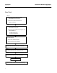
Instruction Manual Supplement DVC6000 SIS January 2011 D103285X012 Flow Chart Step 1 Check for proper mounting of the DVC6000 SIS to the actuator Check to ensure that sufficient air supply is available Step 2 Check for Input Signal, referencing the DVC6000 SIS nameplate Apply the appropriate electrical power to the DVC6000 SIS • 4‐20 mA for PT‐PT • 0‐24 VDC for MULTI Step 3 Run Setup Wizard Run Auto Travel Calibration Run Partial Stroke Calibration Step 4 Perform Step Response Tes
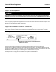
Instruction Manual Supplement D103285X012 DVC6000 SIS January 2011 Step 1: Visual Inspection WARNING These guidelines assume that the DVC6000 SIS is properly mounted on the actuator. Improper mounting and installation could result in personal injury or property damage. Refer to the Installation section of the DVC6000 SIS Instruction Manual for additional information.
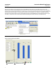
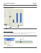
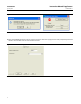
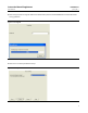
Instruction Manual Supplement DVC6000 SIS January 2011 D103285X012 Use ValveLink software to communicate with the DVC6000 SIS. Select Status from the Diagnostics menu. Start monitoring the status of the DVC6000 SIS and check for its control mode. If the operational mode on the nameplate is PT-PT the control mode should be Analog, as shown in figure 3. If the operational mode on the nameplate is MULTI the control mode should be Digital, as shown in figure 4.
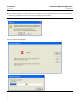
Instruction Manual Supplement DVC6000 SIS D103285X012 January 2011 Figure 4. Multi‐Drop Control Mode DIP SWITCH SET TO MULTI END MONITORING Step 3: Setup Wizard Run Setup Wizard. Select Setup Wizard from the Instrument Setup menu or click on the Setup Wizard icon on the tool bar. ValveLink software will prompt you to set the DVC6000 SIS out of service. Figure 5.
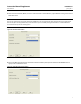
DVC6000 SIS January 2011 Instruction Manual Supplement D103285X012 Figure 6. Set the Instrument Out of Service After the DVC6000 SIS has been set out of service enter the maximum supply pressure when prompted by ValveLink software. Click on Next once the value has been entered. Figure 7.
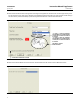
Instruction Manual Supplement D103285X012 DVC6000 SIS January 2011 Select the Actuator Make, Model, and Size. Check the box if a Volume Booster / Quick Release is being used. Click on Next when done. Note The use of a Quick Exhaust Valve (QEV) with the DVC6000 SIS is not recommended for safety instrumented system applications. The use of a QEV in an SIS application may cause the valve to cycle or instability during partial stroke test. A Volume Booster is recommended to improve the stroking speed.
DVC6000 SIS Instruction Manual Supplement January 2011 D103285X012 Select the Partial Stroke Test Starting Point according to the application. Remove cover to check type of relay used. Ensure that the correct relay type is selected as this will affect the Partial Stroke Test. Verify that the actual tubing is the same as the pneumatic hookup represented by ValveLink software. Click on Next when done. Figure 10.
Instruction Manual Supplement D103285X012 DVC6000 SIS January 2011 Select the appropriate Tuning Set. Refer to the Detailed Setup section of the DVC6000 SIS Instruction Manual for tuning guidelines. Figure 12. Tuning Set Select Yes to use Factory Defaults for Setup. Figure 13.
DVC6000 SIS January 2011 Instruction Manual Supplement D103285X012 When the Setup Wizard is complete, you will be prompted to run Auto Travel Calibration. Click Yes to proceed with calibration (suggested if this is the initial setup of the digital valve controller). Figure 14. Run Auto Travel Calibration Figure 15.
Instruction Manual Supplement D103285X012 DVC6000 SIS January 2011 Once Auto Travel Calibration is complete, Partial Stroke Calibration will automatically run. Figure 16. Partial Stroke Calibration Choose the desired stroke speed for Partial Stroke Calibration, then click OK to finish calibration. Larger actuators may require a slower test speed. Figure 17. Choose Desired Test Speed Put the DVC6000 SIS In Service once calibration is complete. Figure 18.
DVC6000 SIS Instruction Manual Supplement January 2011 D103285X012 Step 4: Step Response Test Put the DVC6000 SIS Out of Service to run the Step Response Test. Select Step Response from the Diagnostics menu. Figure 19. Run Step Response Test Run a 3 step Step Response test to check the response of the actuator; 0% - 100% - 0%. Figure 20.
Instruction Manual Supplement DVC6000 SIS D103285X012 January 2011 Check the resulting graph to determine if the Step Response test results meets requirements. Step Response with Supply Pressure and Drive Signal graphs are also available. Click on Save Dataset to save the test results to a file. Figure 21.
DVC6000 SIS Instruction Manual Supplement January 2011 D103285X012 Step 5: Total Scan Select Spec Sheet and fill in the information under the Valve, Trim, and Actuator tabs. Click on Save Spec Sheet when finished. Figure 22. Spec Sheet FILL IN THE INFORMATION UNDER THE VALVE, TRIM, AND ACTUATOR TABS SAVE SPEC SHEET Put the DVC6000 SIS Out of Service to run the Dynamic Scan. Select Dynamic Scan > Total Scan from the Diagnostics menu. Figure 23.
Instruction Manual Supplement D103285X012 DVC6000 SIS January 2011 Click on Run Diagnostic to start the Total Scan. Figure 24. Total Scan CLICK TO RUN DIAGNOSTIC Check the graphs to see if the Valve Signature, Dynamic Error Band, and Drive Signal results are acceptable. Click on Save Dataset to save the test results to a file. Figure 25.
Instruction Manual Supplement DVC6000 SIS January 2011 D103285X012 Step 6: Partial Stroke Test Select Partial Stroke > Ramp under the Diagnostics menu, as shown below, or Click on the Partial Stroke Ramp icon on the tool bar. Note If there is previous test data present in the microprocessor memory it will be automatically retrieved at this point. Figure 26.
Instruction Manual Supplement DVC6000 SIS D103285X012 January 2011 Verify that the test parameters are correct. Figure 27. Verify Test Parameters THESE VALUES ARE USED AS AN EXAMPLE ONLY. REFER TO PARTIAL STROKE VARIABLE IN THE DETAILED SETUP SECTION OF THE DVC6000 SIS INSTRUCTION MANUAL (D103230X012) FOR ADDITIONAL INFORMATION ON VALVE TEST PARAMETERS Click on Run Diagnostic, then OK when you are prompted with the Warning screen. Figure 28.
Instruction Manual Supplement DVC6000 SIS January 2011 D103285X012 If any Partial Stroke Test data is present in the microprocessor memory, it will be automatically uploaded when Partial Stroke Ramp is selected in ValveLink software. Figure 30. Partial Stroke Upload Progress Once the test is run/uploaded completely, click on the Notes tab to type in the test name. Click on Save Dataset to the save the Partial Stroke Test results. Click on the Graph tab and select Valve Signature. Figure 31.
Instruction Manual Supplement D103285X012 DVC6000 SIS January 2011 Click on the Signature Analyzer button to analyze friction of the valve. Signature Analyzer serves as a tool to check on valve performance. Note Signature Analyzer is available clicking on the Save Dataset button after completion of the Partial Stroke Test. Figure 32.
Instruction Manual Supplement DVC6000 SIS January 2011 D103285X012 Clicking on the Add Overlay button allows you to overlay a graph from a previously saved dataset on top of the graph currently displayed. Overlay the resulting graph with previous graphs and look for any inconsistencies. Overlay the most recent test graph and look for any inconsistencies. Overlay the initial (oldest date) test graph and look for any inconsistencies. Figure 33.
Instruction Manual Supplement D103285X012 DVC6000 SIS January 2011 Step 7: Protection If this is the final set up / configuration before the DVC6000 SIS is put into service Protection should be set for “Configuration and Calibration” to protect for any inadvertent acts as per the appropriate DVC6000 SIS Safety Manual. When protection is enabled for “Calibration and Configuration” calibration is prohibited and protected setup parameters cannot be changed.
DVC6000 SIS January 2011 Instruction Manual Supplement D103285X012 To disable protection, select Change Protection from the Instrument Setup menu. Follow the prompts to disable protection. Figure 36.
Instruction Manual Supplement D103285X012 DVC6000 SIS January 2011 Figure 36. Disable Protection (continued) Set DVC6000 SIS protection to Configuration & Calibration. Once protection is enabled, the digital valve controller is ready for installation and commissioning. Figure 37.
DVC6000 SIS Instruction Manual Supplement January 2011 D103285X012 Related Documents Bulletin 62.