
Data Sheet
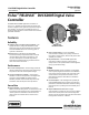

DVC6200f Digital Valve Controller
D103399X012
Product Bulletin
62.1:DVC6200f
July 2013
3
Specifications
Available Mounting
J Integral mounting to the Fisher GX Control
Valve and Actuator System
J Integral mounting to Fisher rotary actuators,
J Sliding‐stem linear applications
J Quarter‐turn rotary applications
DVC6200f digital valve controllers can also be mounted
on other actuators that comply with IEC 60534‐6‐1,
IEC 60534‐6‐2, VDI/VDE 3845 and NAMUR mounting
standards
Function Block Suites
J SC (Standard Control) (throttling control)
Includes AO, PID, ISEL, OS, AI, MAI, DO,
and four DI function blocks
J FC (Fieldbus Control) (throttling control)
Contains the AO function block
J FL (Fieldbus Logic) [discrete (on/off) connectivity]
Includes DO, and four DI function blocks
Block Execution Times
AO Block: 15 ms AI Block: 15 ms
PID Block: 20 ms MAI BLock: 35 ms
ISEL Block: 20 ms DO Block: 15 ms
OS Block: 20 ms DI Block: 15 ms
Electrical Input
Voltage Level: 9 to 32 volts
Maximum Current: 19 mA
Reverse Polarity Protection: Unit is not polarity sensitive
Termination: Bus must be properly terminated per ISA
SP50 guidelines
Digital Communication Protocol
F
OUNDATION fieldbus registered device
Physical Layer Type(s):
121—Low‐power signaling, bus‐powered, Entity
Model I.S.
511—Low‐power signaling, bus‐powered, FISCO I.S.
Fieldbus Device Capabilities
Backup LAS (Link Active Scheduler)
Supply Pressure
(1)
Minimum Recommended: 0.3 bar (5 psig) higher than
maximum actuator requirements
Maximum: 10.0 bar (145 psig) or maximum pressure
rating of the actuator, whichever is lower
Supply Medium
Air or Natural Gas
Air: Supply pressure must be clean, dry air that meets
the requirements of ISA Standard 7.0.01.
Natural Gas: Natural gas must be clean, dry, oil‐free, and
noncorrosive. H
2
S content should not exceed 20 ppm.
A maximum 40 micrometer particle size in the air
system is acceptable. Further filtration down to 5
micrometer particle size is recommended.
Output Signal
Pneumatic signal, up to full supply pressure
Minimum Span: 0.4 bar (6 psig)
Maximum Span: 9.5 bar (140 psig)
Action:
JDouble, JSingle Direct or JReverse
Steady-State Air Consumption
(2)(3)
At 1.4 bar (20 psig) supply pressure: Less than
0.38 normal m
3
/hr (14 scfh)
At 5.5 bar (80 psig) supply pressure: Less than
1.3 normal m
3
/hr (49 scfh)
Maximum Output Capacity
(2)(3)
At 1.4 bar (20 psig) supply pressure: 10.0 normal m
3
/hr
(375 scfh)
At 5.5 bar (80 psig) supply pressure: 29.5 normal m
3
/hr
(1100 scfh)
Operating Ambient Temperature Limits
(1)(4)
-40 to 85_C (-40 to 185_F)
-52 to 85_C (-62 to 185_F) for instruments utilizing the
Extreme Temperature option (fluorosilicone
elastomers)
Independent Linearity
(5)
Typical Value: ±0.50% of output span
Electromagnetic Compatibility
Meets EN 61326-1 (First Edition)
Immunity—Industrial locations per Table 2 of the
EN 61326-1 standard.
Emissions—Class A
ISM equipment rating: Group 1, Class A
Vibration Testing Method
Tested per ANSI/ISA-S75.13.01 Section 5.3.5.
Humidity Testing Method
Tested per IEC 61514‐2
-continued-