
Instruction Manual

www.Fisher.com
Module Definitions, IO Bytes, and Data Length
for FIELDVUE™ DVC6200p PROFIBUS PA Digital
Valve Controller
Contents
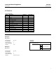
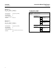
AO Module 3..................................
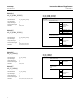
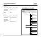
AI Module 8...................................
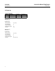
DO Module 9..................................
DI Module 10..................................
A GSD file contains information about the device capabilities.
Modules are defined within the GSD. Each module represents a distinct sub set of parameter values for a specific
function block in the DVC6200p; each function block can have one or more modules defined.
Slots originate in the Class 1 Master (Configuration Host) and represent an address range of bytes. Typically, slots will
define address ranges for Input values (I) and other address ranges for Output values (Q).
If a Slot is not used it must NOT be null or blank. It must be assigned as an Empty Module.
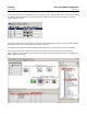
Modules are assigned to specific Slots. For example any of the AO modules must be assigned to Slot 1. If a DO module
is required it must be assigned to Slot 3. The slot assignments are defined in the device GSD file FC051037.gsd.
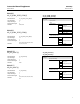
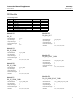
Slot Definition
Module
Slot (1) = AO 21 1,2,3,4,5,6,7,8,9,10,11,12,13,14,15
Slot (2) = AI 16 1,16,17
Slot (3) = DO 18 1,18,19,20,21,22,23,24
Slot (4) = DI 1 1 25 1,25
Slot (5) = DI 2 2 25 1,25
Note
The AO module is always assigned to the first slot. In some systems the first slot is defined as 0; consequently the AO module will
be defined as Slot 0, the AI module will be defined as Slot 1, etc.
Instruction Manual Supplement
D104019X012
DVC6200p
November 2014