
Instruction Manual


Instruction Manual
D103198X012
i2P-100 Transducer
July 2014
12
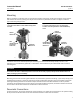
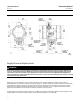
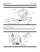
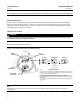
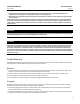
Figure 5. Dimensions and Connections
58.7
(2.31)
22.3
(0.88)
75.2
(2.96)
55.7
(2.19)
33.3
(1.31)
67.8
(2.67)
75.7
(2.98)
22.9
(0.90)
33.3
(1.31)
33.3
(1.31)
67 (2.62) CAP
REMOVAL
CLEARANCE
67 (2.62) CAP
REMOVAL
CLEARANCE
1/4 18 NPT
SUPPLY
CONNECTION
1/2 14 NPT
CONDUIT
CONNECTION
81.6
(3.21)
74.2
(2.92)
34.7
(1.37)
98.7
(3.89)
mm
(INCH)
GE0643
(sheet 1 of 4)
1/4 18 NPT
OUTPUT
CONNECTION
103.9
(4.09)
103.9
(4.09)
36.3
(1.43)
1/4 18 NPT
OUTPUT
CONNECTION
1/4 18 NPT VENT
OR PIPE‐A‐WAY
CONNECTION
Supply Pressure Requirements
WARNING
Severe personal injury or property damage could result from an unstable process if the instrument supply medium is not
clean, dry, oil‐free and noncorrosive. While use and regular maintenance of a filter that removes particles larger than 40
micrometers in diameter will suffice in most applications, check with an Emerson Process Management field office and
industry instrument air quality standards for use with corrosive air or if you are unsure about the proper amount or method
of air filtration or filter maintenance.
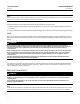
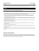
Supply pressure must be clean, dry air or noncorrosive gas. Use a Fisher 67CFR filter regulator with standard 5
micrometer filter, or equivalent, to filter and regulate supply air. The filter regulator can be mounted on a bracket with
the transducer as shown in figure 6 or mounted on the actuator mounting boss. An output pressure gauge may be
installed on the regulator to indicate the supply pressure to the transducer. Also, as an aid for calibration, a second
gauge may be installed on the transducer to indicate transducer output pressure.
Connect the nearest suitable supply source to the 1/4 NPT IN connection on the filter regulator (if furnished) or to the
1/4 NPT SUPPLY connection on the transducer case (if the filter regulator is not attached).