
Instruction Manual


Instruction Manual
D103198X012
i2P-100 Transducer
July 2014
20
3. If a filter/regulator is used, ensure that it is working correctly. If not, ensure the dripwell is not plugged because of
excessive moisture accumulation. If necessary, drain off any moisture, and clean or replace the filter element.
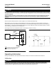
4. Force the converter module to maximum output pressure with a 30 mA DC signal. Output pressure should build up
to the approximate value of the supply pressure [maximum of 3.4 bar (50 psi)].
5. When the input current is removed, the transducer output pressure should drop to less than 0.14 bar (2 psig). If it
does not, check to ensure the vent and exhaust air passageway is free from foreign material.
6. To inspect the relay assembly, refer to the Relay Maintenance procedures in this manual.
7. If the problem has not been resolved, see Converter Module Replacement in this manual.
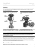
Converter Module Replacement
Removal
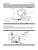
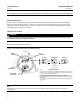
Refer to figure 13 for key number locations.
1. Disconnect operating lines providing air pressure, electric power, or a control signal to the actuator. If using gas as
the supply medium remove electrical power before removing the housing cap.
2. Remove the housing cap (key 2) (the cap farthest away from the conduit). Note that the set screw associated with
this housing cap (key 8) needs to be loosened to remove the cap.
3. Unscrew the two captive screws (key 52) and remove the converter module from the housing.
4. Inspect the O‐ring (key 55) and replace if necessary.
Replacement
1. Lubricate the O‐ring (key 55) with a silicone sealant before replacing the converter module in the housing.
2. Insert the converter module into position in the housing (key 1). Replace the two screws (key 52) and tighten them.
3. Replace the housing cap (key 2), making sure to re‐tighten the set screw (key 8).
4. Electrically calibrate the unit using the procedure in the Calibration section of this manual.
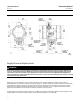
Electronics Module Replacement
Removal
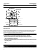
Refer to figure 13 for key number locations.
1. Disconnect operating lines providing air pressure, electric power, or a control signal to the actuator. If using gas as
the supply medium remove electrical power before removing the housing cap.
2. Remove the housing cap (key 2) (the cap closest to the conduit). Note that the set screw (key 8) associated with this
housing cap needs to be loosened to remove the cap.
3. Note the location of the wires, then remove the electrical wiring from the terminal block.
4. Remove the three screws (key 26) and remove the electronics module from the housing.
Replacement
1. Insert the electronics module into position in the housing (key 1). Replace the three screws (key 26) and tighten
them.
2. Replace the electrical wiring removed in step 1 of the removal procedures. Do not overtighten the terminal screws.
Maximum torque is 0.45 NSm (4 lbfSin).