
Instruction Manual


Instruction Manual
D103198X012
i2P-100 Transducer
July 2014
22
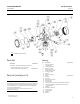
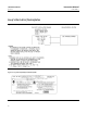
1. Assemble the inner valve spring (key 35) onto the body plug (key 32) and fit the valve plug (key 39) onto the inner
valve spring as shown in figure 12. To assure best alignment between the valve plug, inner valve spring, and body
plug; fit the valve plug onto the inner valve spring so that one of the three tabs at the base of the valve plug sets at
the end of the last coil of the inner valve spring.
2. Lubricate the O‐ring (key 42) with a silicone sealant (key 37). Insert the assembled valve plug, inner valve spring,
and body plug into the relay body (key 41). Compress the spring and thread the body plug (key 5) into place. Then,
tighten the body plug.
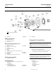
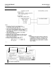
3. Insert two of the mounting screws (key 36) into two opposite holes of the relay body (key 41). Hold the screws in
place while assembling the following parts on the relay body. The screws serve as studs to align the parts as they are
being assembled.
4. When replacing the exhaust port assembly (key 33), make sure all passages and screw holes are aligned and that
the hole in the center of the exhaust port assembly fits over the valve plug (key 39). Place the exhaust port assembly
on the relay body (key 41). Hold assembled parts in place.
5. Make sure the tabs on the body block (key 40) align with the tabs on the relay body (key 41) and that the side with 5
holes faces the relay body. Place the body block on the assembled parts. Hold assembled parts in place.
6. When replacing the input diaphragm (key 38), make sure all passages and screw holes are aligned. Place the input
diaphragm on the body block (key 40). Hold assembled parts in place.
7. Install the bias spring (key 34) into the transducer housing assembly (key 1). Make sure the tabs on the body block
and relay body align with the tab on the transducer housing assembly. Place the assembled parts onto the
transducer housing assembly. Thread the two mounting screws (key 36) into the transducer housing assembly.
Install the remaining two mounting screws. Tighten all mounting screws to 2 NSm (20 lbfSin).
8. Perform the procedure in the Calibration section of this manual.
Parts Ordering
A serial number is assigned to each transducer and stamped on the nameplate. Always refer to this serial number when
corresponding with your Emerson Process Management sales office regarding spare parts or technical information.
When ordering replacement part, also specify the complete 11‐character part number from the Parts list.
WARNING
Use only genuine Fisher replacement parts. Components that are not supplied by Emerson Process Management should
not, under any circumstances, be used in any Fisher instrument. Use of components not supplied by Emerson Process
Management may void your warranty, might adversely affect the performance of the instrument, and could cause personal
injury and property damage.