Installation Guide D102800X012 October 2010 Installing ValveLink Software ValveLink Solo AMS ValveLink SNAP-ON ValveLink DTM ValveLink PLUG-IN for PRM www.Fisher.
This page intentionally left blank.
Comment Form ValveLink Software Installation Guide The ValveLink Software Installation Guide is intended to provide the basic information you need to install ValveLink software and associated hardware and software. Detailed information about ValveLink software is provided in the online help. Please give us your feedback to help us improve this guide.
Identify any areas that you found difficult to understand.
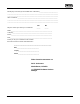
Table of Contents Introduction . . . . . . . . . . . . . . . . . . . . . . . . . . . . . . . . . . . . . 1-1 What is ValveLink Software? . . . . . . . . . . . . . . . . . . . . . 1-3 About this Guide . . . . . . . . . . . . . . . . . . . . . . . . . . . . . . . 1-3 Organization . . . . . . . . . . . . . . . . . . . . . . . . . . . . . . . . . . . 1-4 Before Installing ValveLink Software . . . . . . . . . . . . . . 1-5 Technical Support . . . . . . . . . . . . . . . . . . . . . . . . . . . . . .
Enabling the License of Installed Software . . . . . . . . . 7-3 Attaching the Hardware Key . . . . . . . . . . . . . . . . . . . . . 7-4 Obtaining a Software License Key for a Fresh Installation . . . . . . . . . . . . . . . . . . . . . . . . . . . . . . 7-4 Adding Features to the Installed Software . . . . . . . . . 7-8 Obtaining a Software License Key for a StepUp . . . . 7-9 Removing a License . . . . . . . . . . . . . . . . . . . . . . . . . . . . 7-11 Transferring a License to Another Computer . . . .
Installing Software and Hardware for Communication with FOUNDATION fieldbus Instruments for ValveLink Solo . . . . . . . . . . . . . . . . . . . . . . . . . . . . . . . . . . . . . . . . . 10-1 NI-FBUS Installation . . . . . . . . . . . . . . . . . . . . . . . . . . . . 10-2 Software . . . . . . . . . . . . . . . . . . . . . . . . . . . . . . . . . . . . 10-2 Hardware . . . . . . . . . . . . . . . . . . . . . . . . . . . . . . . . . . . 10-2 Configuring the PCMCIA-FBUS Card . . . . . . . . . . . . .
ValveLink Software
Introduction11 Section 1 This section is an overview of ValveLink software and this guide. What is ValveLink Software? . . . . . . . . . . . . . . . . . . . . . 1-2 About this Guide . . . . . . . . . . . . . . . . . . . . . . . . . . . . . . . 1-3 Organization . . . . . . . . . . . . . . . . . . . . . . . . . . . . . . . . . . . 1-4 Before Installing ValveLink Software . . . . . . . . . . . . . . 1-5 Technical Support . . . . . . . . . . . . . . . . . . . . . . . . . . . . . . 1-6 Related Documents . . .
What is ValveLink Software? ValveLink software is a Windows software package that communicates with HART and FOUNDATION fieldbus FIELDVUE digital valve controllers. ValveLink software supports access to the information available from DVC2000, DVC6000, DVC6000f, DVC6200, and DVC6200f digital valve controllers, and obsolete DVC5000 and DVC5000f digital valve controllers.
About This Guide This installation guide contains easy-to-follow instructions that will guide you through the installation of communications hardware and ValveLink software. Refer to the help system for ValveLink software functions. Scope This guide describes: Installing ValveLink software. Includes ValveLink Solo, AMS ValveLink SNAP-ON, ValveLink DTM, and ValveLink PLUG-IN for PRM.
Organization This guide is organized into the following sections: Section 1, Introduction, describes ValveLink software and this installation guide for ValveLink Solo, AMS ValveLink SNAP-ON, ValveLink DTM, and ValveLink PLUG-IN for PRM. Section 2, Prerequisites and Requirements, gives “before you begin” information, lists installation tools and device documentation, and charts system requirements. Section 3, Installing ValveLink Solo, explains how to install ValveLink Solo.
Before Installing ValveLink Software To successfully install and use ValveLink software, you should: Be familiar with the basics of using Microsoft Windows. Be familiar with the installation and function of basic network communications devices and process control instruments. Have experience using AMS Device Manager if installing AMS ValveLink SNAP-ON. Have experience using using an FDT frame application if installing ValveLink DTM software.
For Technical Support If you have problems or questions that you cannot resolve while using ValveLink software guides or help, ValveLink software technical assistance is available. Support Directory For ValveLink software Technical Support, contact your Local Business Partner. Find them online at: www.valvelink.com and select Contact Sales.
Related Documents FIELDVUE DVC2000 Digital Valve Controller Instruction Manual (D103176X012) FIELDVUE DVC2000 Digital Valve Controller Quick Start Guide (D103203X012) FIELDVUE DVC5000 Series Digital Valve Controller Instruction Manual (D200442X012) (Obsolete product. Contact your Emerson Process Management sales office if a copy of this manual is needed.) FIELDVUE DVC5000 Series Digital Valve Controllers Quick Start Guide (D102700X012) (Obsolete product.
1-8 ValveLink Software
Prerequisites and Requirements2 Section 2 2 This section is an overview of prerequisites and requirements for installation of ValveLink software. “Before You Begin” Information . . . . . . . . . . . . . . . . . . 2-2 Installation Tools and Device Documentation . . . . . . . 2-3 Personal Computer Requirements . . . . . . . . . . . . . . . . 2-4 Supported Operating Systems . . . . . . . . . . . . . . . . . . . 2-6 Compatible Devices . . . . . . . . . . . . . . . . . . . . . . . . . . . .
Before You Begin The complete ValveLink software installation process includes several steps, some of them dependent on the personal computer system that will run ValveLink software and its configuration. In order to successfully install and run ValveLink software, it is important that you follow all of the appropriate steps covered in this installation guide.
Installation Requirements Before you begin the installation procedure outlined in this guide, make sure you have the following items available: ValveLink software installation media (CD-ROM) AMS Suite: Intelligent Device Manager v8.0 or later if installing AMS ValveLink SNAP-ON Frame application supporting FDT 1.2 and addendum if installing ValveLink DTM Yokogawa Plant Resource Manager (PRM) if installing ValveLink PLUG-IN for PRM Licensing USB hardware key, if available.
Personal Computer Requirements ValveLink software, v11.1, has been tested on computers manufactured by Dell, Inc. However, ValveLink software runs on any personal computer or notebook computer equipped with the following software and hardware features. Note ValveLink software, v11.1, will not run on a personal computer using the Windows 95 operating system and is not supported on Windows 98, Windows Me, or Windows NT operating systems.
Modbus communications require the following Standard RS-232 Port Additional HART Interface (see above) FOUNDATION Fieldbus communications require at least one of the following National Instruments Fieldbus H1 interfaces: NI USB-8486 PCI-FBUS/2 PCMCIA-FBUS/2 Series 2 Note Desktop PCs typically require a PCI interface; laptop PCs require a PCMCIA interface.
Supported Operating Systems ValveLink Solo Windows 2000, Windows XP, Windows Vista, Windows 7 operating systems (32 bit), Windows Server 2003 and Windows Server 2008. AMS ValveLink SNAP-ON Operating Systems supported by AMS Suite: Intelligent Device Manager v8.1 and later ValveLink DTM FDT Frame application using Windows 2000, Windows XP, Windows Vista, Windows 7 (32 bit), Windows Server 2003, and Windows Server 2008.
Compatible Devices ValveLink Software communicates with: HART-based DVC2000, DVC6000, DVC6200, or obsolete DVC5000 digital valve controllers via a HART modem or HART multiplexers FOUNDATION fieldbus DVC6000f or DVC6200f digital valve controllers or obsolete DVC5000f digital valve controllers (with firmware revision 7 or later) over an H1 segment.
Installation Options for ValveLink Software Installation options for ValveLink software include: ValveLink Solo AMS ValveLink SNAP-ON ValveLink DTM ValveLink PLUG-IN for PRM Note ValveLink Solo, ValveLink DTM, and ValveLink PLUG-IN for PRM cannot be installed on the same PC. ValveLink Solo and AMS ValveLink SNAP-ON installed on the same PC. At the beginning of the installation process, you can specify how you want the software installed.
Installing ValveLink Solo 3 Section 3 3 This section describes ValveLink Solo installation. ValveLink Solo Installation Overview . . . . . . . . . . . . . . 3-2 Installing the Software . . . . . . . . . . . . . . . . . . . . . . . . . . 3-4 Re-installing the Software . . . . . . . . . . . . . . . . . . . . . . .
ValveLink Solo Installation Overview For further information about ValveLink Solo software and hardware installation: For using the License Wizard program, see page 7-2. A USB hardware key may be used for the licensing of ValveLink Solo. See page 7-4 for instructions on attaching the USB hardware key. If a USB hardware key is not available, a software license key is needed to enable the license of ValveLink Solo. See page 7-4 for instructions on obtaining a software license key.
Table 3-1.
Installing ValveLink Solo Note You cannot copy the installed program files to another computer or to another directory or hard disk. ValveLink Solo will not work if the installed program files are copied to another computer, directory, or hard disk. You cannot move installed programs to another computer; doing so will invalidate your ValveLink software license.
Step 2: Insert the CD into the CD drive of your computer. If the drive’s auto run is enabled, the install wizard will start automatically. Follow the prompts on the screen to start the installation process. If auto run is disabled, start the install from the run window; Select Start > Run from the taskbar. In the text box, type D:SETUP.EXE (where D is the CD-ROM drive letter). Click OK and follow the prompts.
Re-installing the Software If you are re-installing ValveLink Solo, remember: It is not necessary to uninstall a previous version of the program. The version you are installing will overwrite an older version of the program and use the existing license. Restart your computer before running the ValveLink software installation program so a complete, clean installation is possible. The ValveLink software installation process allows you to save an existing database.
Section 4 Installing AMS ValveLink SNAP-ON44 This section describes the installation of AMS ValveLink SNAP-ON. AMS ValveLink SNAP-ON Installation Overview . . . . 4-2 Installing AMS ValveLink SNAP-ON . . . . . . . . . . . . . . 4-3 Starting AMS ValveLink SNAP-ON . . . . . . . . . . . . . . .
AMS ValveLink SNAP-ON Installation Overview AMS ValveLink SNAP-ON is a software application that is installed as an integral part of AMS Suite: Intelligent Device Manager to extend its functionality. AMS ValveLink SNAP-ON adds the diagnostic test capabilities of ValveLink software to AMS Device Manager. A USB hardware key is not used for installing AMS ValveLink SNAP-ON. However, AMS Device Manager must be licensed for the AMS ValveLink SNAP-ON. Table 4-1 shows AMS ValveLink SNAP-ON capabilities.
Installing AMS ValveLink SNAP-ON To install AMS ValveLink SNAP-ON, you must first have installed a properly licensed copy of AMS Device Manager. Then, follow the steps below to install AMS ValveLink SNAP-ON. Note To install AMS ValveLink SNAP-ON, you must log on to the PC running AMS Device Manager as Administrator or as a user with Administrator privileges. Step 1: Close all open applications on your desktop. Step 2: Insert the CD with AMS ValveLink SNAP-ON into the CD-ROM drive of your computer.
Starting AMS ValveLink SNAP-ON Follow these steps to start AMS ValveLink SNAP-ON: CAUTION Do not run ValveLink Solo at the same time you are using AMS Device Manager or AMS ValveLink SNAP-ON. Running both simultaneously may cause communication errors. Note To successfully use AMS ValveLink SNAP-ON, you must be familiar with using AMS Device Manager. Refer to the AMS online User’s Guide and online Help for information.
HART Device: Step 3: The AMS Explorer or Device Connection View window (figure 4-2) displays. Step 4: AMS displays the communication devices (modem, multiplexer) that are connected to the PC running AMS and the AMS ValveLink SNAP-ON. Right-click the device icon and select Scan All Devices to locate connected HART instruments. Communication Devices Figure 4-2.
Fieldbus Device: Step 6: In the Device View Connection window, right click the instrument icon and select SNAP-ON/Linked Apps > ValveLink from the context menu as shown in figure 4-4. Figure 4-4.
5 Section 5 Installing ValveLink DTM 5 This section describes the installation of ValveLink DTM. ValveLink DTM Installation Overview . . . . . . . . . . . . . . 5-2 Installing ValveLink DTM . . . . . . . . . . . . . . . . . . . . . . . . 5-3 Starting ValveLink DTM . . . . . . . . . . . . . . . . . . . . . . . . .
ValveLink DTM Installation Overview The ValveLink DTM is part of an open solution for field device management that enables configuration, monitoring, calibration, diagnostics and testing of FIELDVUE digital valve controllers. A USB hardware key or a software license key is required for enabling the license of ValveLink DTM software. Note Frame application supporting FDT 1.2 and addendum is required. Table 5-1 shows ValveLink DTM capabilities. Table 5-1.
Installing ValveLink DTM To install ValveLink DTM: Note A USB hardware key or a software license key is required for installation of ValveLink DTM software. If available, locate the USB hardware key to use while running the License Wizard. If a USB hardware key is not available, see Section 7 for instructions for obtaining a software license key. For instructions on attaching the USB hardware key see page 7-4 of this Installation Guide. Step 1: Close all open applications on your desktop.
Starting ValveLink DTM Follow these steps to start the ValveLink DTM: Note To successfully use the ValveLink DTM, you must be familiar with using the FDT frame application used to launch the ValveLink DTM. This section covers one example. Refer to the users guide for the FDT frame application that the ValveLink DTM is installed with for additional information. Step 1: Start the FDT frame application. Step 2: Select Add Device, as shown in figure 5-1, and click on the appropriate CommDTM. Select OK.
Step 3: With the CommDTM highlighted, select Add Device, as shown in figure 5-2, and click on the appropriate Device DTM. Select OK. Add Device Figure 5-2. Select the DeviceDTM Step 4: Set the appropriate settings for the CommDTM and DeviceDTM (see figure 5-3 and 5-4). Figure 5-3.
Figure 5-4. Setting the DeviceDTM Step 5: With the DeviceDTM highlighted, select Connect as shown in figure 5-5. Connect Figure 5-5.
Step 6: Once connected, select ValveLink DTM as shown in figure 5-6. Right Click on the Device Type and Select Additional functions to Access ValveLink DTM Figure 5-6.
Step 7: The ValveLink DTM will launch in a new window. All devices currently connected in the FDT frame application will show in the tree menu to the left of the ValveLink DTM window, as shown in figure 5-7. Double-click the device to open the device tag. Double-Click to open the device tag Figure 5-7.
Section 6 Installing ValveLink PLUG-IN for PRM66 This section describes the installation of ValveLink PLUG-IN for PRM. ValveLink PLUG-IN for PRM Installation Overview . . . . . . . . . . . . . . . . . . . . . . . . . . 6-2 Installing ValveLink PLUG-IN for PRM . . . . . . . . . . . . 6-3 Starting ValveLink PLUG-IN for PRM . . . . . . . . . . . . .
ValveLink PLUG-IN for PRM Installation Overview ValveLink PLUG-IN for PRM is a software application that is installed as an integral part of Plant Resource Manager (PRM) to enhance system functionality. ValveLink PLUG-IN for PRM adds the diagnostic test capability of ValveLink Software to PRM. A USB hardware key or a software license key is required for enabling the license of ValveLink PLUG-IN for PRM. Table 6-1 shows ValveLink PLUG-IN for PRM capabilities. Table 6-1.
Installing ValveLink PLUG-IN for PRM To install ValveLink PLUG-IN for PRM: Note ValveLink PLUG-IN for PRM requires PRM 2.06 or later. Note A USB hardware key or a software license key is required for the installation of ValveLink PLUG-IN for PRM. If available, locate the hardware key to use while running the License Wizard. If a USB hardware key is not available, see Section 7 for instruction for obtaining a software license key.
Step 7: You are given the option to keep the old database or to replace the existing database, as shown in figure 6-1. After making your selection, click Next to continue. Figure 6-1. Existing Database Step 8: A progress bar displays as ValveLink PLUG-IN for PRM is installed as shown in figure 6-2. Figure 6-2. Progress Bar Step 9: At the end of the installation process, Installation will automatically register ValveLink PLUG-IN for PRM with PRM by running the batch file, as shown in figure 6-3.
Step 10: If you are installing ValveLink PLUG-IN for PRM for the first time, you will be prompted to run the License Wizard at the end of the installation process. Select OK and follow the prompts on the screen, or select Cancel and run the License Wizard later. See Section 7 for details on running the License Wizard. Figure 6-4.
Starting ValveLink PLUG-IN for PRM Follow these steps to start ValveLink PLUG-IN for PRM: Note To successfully use ValveLink PLUG-IN for PRM, you must be familiar with using PRM software. Step 1: Run the PRM application. Step 2: Select a Fisher fieldbus digital valve controller from the PRM system. Step 3: Click on the PLUG-IN tab. Move the mouse cursor to the white list box, as shown in figure 6-5 and right-click. Select the Insert Ctrl+Ins option. PLUG-IN Tab Insert Ctrl+Ins Figure 6-5.
Step 4: Select ValveLink PLUG-IN Launcher from the Tool Name dialog box and click on the OK button. Figure 6-6. Tool Name Dialog Box Step 5: Select ValveLink PLUG-IN Launcher and click on execute to start ValveLink PLUG-IN for PRM. Figure 6-7.
6-8 ValveLink Software
ValveLink License Wizard7 Section 7 7 This section describes the ValveLink License Wizard ValveLink License Wizard . . . . . . . . . . . . . . . . . . . . . . . 7-2 Enabling the License of Installed Software . . . . . . . . . Using an installation USB hardware key . . . . . . . . . . Using a software license key . . . . . . . . . . . . . . . . . . . . Software Features . . . . . . . . . . . . . . . . . . . . . . . . . . . . . . 7-3 7-4 7-4 7-6 Adding Features to the Installed Software . . . . . . . . .
ValveLink License Wizard ValveLink License Wizard is a utility that assists you to enable and administer the license of your ValveLink software. The License Wizard program is used to: Activate the ValveLink software license from an installation USB hardware key or from a software license key. Increase the capabilities of the installed ValveLink software. A separate StepUp USB hardware key or a software license key is required to increase the tag limit or add features to the installed software.
Enabling the License of Installed Software ValveLink License Wizard can be used to enable the license of installed ValveLink software. A valid installation USB hardware key or a software license key is required to enable the license of installed ValveLink software. See figure 7-1. Figure 7-1.
To enable the license using an installation USB hardware key: Step 1: Attach your installation USB hardware key to the computer, as shown in figure 7-2. Step 2: Run License Wizard and click on the New License button. Step 3: Select the Generate license using installation hardware key option button (see figure 7-1), and click Next. Follow the License Wizard steps as directed.
Figure 7-3. ValveLink License Wizard Registration Step 5: After receiving the license keys, re-run License Wizard, and continue on with Step 6. Step 6: Click on the Enter License Key button and either import or manually enter the license key received from the ValveLink Registration Center. Follow the License Wizard steps as directed.
Software Features After running License Wizard, the next screen lists the available software features. After confirming that the appropriate features are enabled in your software, select “Yes. I would like to proceed with the above features.”, then click Next. Figure 7-4. Available Software Features HART—When YES, enables communication with a DVC2000, DVC5000, DVC6000, or DVC6200 digital valve controller using a HART modem or over a HART multiplexer network.
Step Response—When YES, allows running a step response diagnostic test, when the user has the diagnostic privilege. The availability of this level is not dependent upon the availability of the standard diagnostics level. Valve Signature—When YES, allows running a valve signature diagnostic test, when the user has the diagnostic privilege and the instrument level is AD. The availability of this level is not dependent upon the availability of the standard diagnostics level.
Adding Features to the Installed Software ValveLink License Wizard can be used to increase the capabilities of the installed ValveLink software. A separate StepUp USB hardware key or a software license key is required to increase the tag limit or add features to the installed software. Note The StepUp From Features in the StepUp USB hardware key or software license key must match with the license. If the features do not match, ValveLink License Wizard will display an error message.
Obtaining a Software License Key for a ValveLink Feature or Tag StepUp ValveLink License Wizard can be used to generate a registration form that can be submitted to ValveLink Registration Center to obtain your license keys for StepUp. Note A software license key cannot be used for obtaining an Instrument StepUp. To generate a registration form for StepUp: Step 1: Unplug the USB hardware key attached to the computer. Step 2: Run License Wizard and click on the StepUp button.
Step 7: Follow the License Wizard steps as directed. Step 8: If the original license was installed with a software license key skip the following steps. Step 9: If the original license was installed with an installation USB hardware key, after successfully upgrading the license, License Wizard will ask you to attach the original installation USB hardware key. Step 10: Unplug any USB hardware keys from the computer before attaching the installation USB hardware key.
Removing a License The license from the installed software can be recovered to the original installation USB hardware key. After successfully removing the license, the installation USB hardware key can be used to enable the license of ValveLink Software installed on another computer. Note The original installation USB hardware key must be attached to your computer’s USB port. The features and the serial number of the original installation USB hardware key must match the license in the installed software.
Transferring a License to another Computer A license from the installed software can be transferred to another computer. Note After successfully generating the license keys for the target computer, the license on the source computer will be removed permanently. You will not be able to run ValveLink software on the source computer. To transfer your license: Step 1: Run License Wizard on the target computer to generate the registration request form.
Updating the USB Hardware Key ValveLink License Wizard can update your original installation USB hardware key with the new StepUp features. The updated USB hardware key can be used to enable a license on another computer. Note The original installation USB hardware key must be attached to your computer’s USB port. The features and the serial number of the original installation USB hardware key must match the license.
Enabling a Temporary License ValveLink License Wizard can grant an emergency temporary license for a maximum period of five (5) days. Note A temporary license must be used only once per machine for a fresh installation. While the temporary license is active, the system clock should not be set back. If the system clock is set to an earlier date and time the temporary license will be disabled. To enable a temporary license: Step 1: Run the License Wizard and click on the Temporary License button.
Entering a License Key After receiving the license key from the ValveLink Registration Center, you must run License Wizard and enable or StepUp the license of the installed ValveLink Software. To enter your license Key: Step 1: Run License Wizard and click on the Enter License Key button, as shown in figure 7-7. Figure 7-7. Enter License Key Step 2: Click on the Import from File button to import the file received by e-mail from the ValveLink Registration Center.
7-16 ValveLink Software
HART Modem Installation for ValveLink Solo Section 8 8 This section is an installation overview of the HART modem. Attaching the HART Modem . . . . . . . . . . . . . . . . . . . . . 8-2 Refer to ValveLink software help for information on selecting HART modem communication.
Attaching the HART Modem The HART modem attaches to the serial port usually found on the back of the personal computer or the USB port. Note HART modem drivers, which are needed for the HART modem to work, are installed during ValveLink software installation. Step 1: Locate the serial port or USB port. If ValveLink Solo setup and installation is complete, connect the modem to the port specified on the Communication page in the Preferences window.
Multiplexer Networks for ValveLink Solo9 Section 9 89 This section is an overview of multiplexer networks. Setting Up a Multiplexer Network . . . . . . . . . . . . . . . . . 9-2 Changing the Multiplexer Tag and Descriptor . . . . . . . 9-4 Setting Up the Pepperl+Fuchs Multiplexer . . . . . . . . . 9-5 Viewing Multiplexers Status . . . . . . . . . . . . . . . . . . . . . . 9-6 Adding Instruments to a Multiplexer . . . . . . . . . . . . . . .
Setting Up a Multiplexer Network ValveLink Solo uses an RS485 network to communicate with FIELDVUE DVC2000, DVC5000, DVC6000, and DVC6200 instruments through HART multiplexers. An RS232-to-RS485 converter is required to connect the serial port (RS232 protocol) on the computer to the RS485 network. Depending upon the multiplexer, ValveLink Solo can support up to 256 individual loop channels per multiplexer. You can connect one instrument to each loop channel.
Step 9: Click the OK button then exit the program and restart to cause changes to take effect. Step 10: Refer to figure 9-1. After restarting the program, right click the Communication icon in the left pane of the window. Step 11: From the drop-down menu select Scan for New. Watch the messages as ValveLink Solo scans the network. You should see the network being scanned.
Changing the Multiplexer Tag and Descriptor To change the multiplexer tag or descriptor, click the Tag & Descriptor button on the Multiplexer Information display. Enter an up to 8 character tag and an up to 16 character descriptor.
Setting Up the Pepperl+Fuchs Multiplexer When adding or removing a submodule from a Pepperl+Fuchs multiplexer you must reconfigure the multiplexer to indicate the changes. Multiplexer configuration changes are made from the Pepperl+Fuchs Module Setup screen, figure 9-2. To setup a Pepperl+Fuchs multiplexer: Step 1: On each Pepperl+Fuchs slave module, set the slave address switch to an unused value so that each module has its own individual setting.
Viewing Multiplexer Status You can view the status and add a tag and descriptor to each multiplexer on the network. For a Pepperl+Fuchs multiplexer, you can also define which modules are included in the multiplexer. Figure 9-3. ValveLink Solo Multiplexer Information Window The following define the fields on the Multiplexer Information window: Mux #—The multiplexer address, determined by the address switch settings on the multiplexer or communications module.
Loop Search—Currently the multiplexer or communications module only searches for single analog loops, those loops where the instrument polling address is 0. Gateway Device—HART signaling scheme. Always RS485 - Bell 202 Software Rev.—Revision number of the software installed in the multiplexer or communications module. Hardware Rev.—Hardware revision level. Retry Count—Number of times multiplexer or communications module attempts to send a command to the instrument.
Adding Instruments to a Multiplexer Note ValveLink Solo must be licensed with a Tag Limit sufficient for the number of connected instruments. See page 7-8 for more information. Depending upon the multiplexer, ValveLink Solo can support up to 256 individual loop channels per multiplexer. You can connect one instrument to each loop channel. To add a new instrument to a multiplexer: Step 1: Connect HART signal wiring to the multiplexer. Step 2: Apply power to the instruments.
Section 10 Installing Software and Hardware for Communication with FOUNDATION fieldbus Instruments for ValveLink Solo10 This section is an overview of installing software and hardware from National Instruments Corporation and setting up communication with FOUNDATION fieldbus instruments. NI-FBUS Installation Software . . . . . . . . . . . . . . . . . . . . . . . . . . . . . . . . . . . . 10-2 Hardware . . . . . . . . . . . . . . . . . . . . . . . . . . . . . . . . . . .
NI-FBUS Installation Before beginning any installation, refer to the Installation Requirements on page 2-3. Connecting to a FOUNDATION fieldbus instrument requires software and hardware supplied by National Instruments Corporation: Fieldbus Interface and Driver (NI-FBUS) software. The installation procedure depends on the operating system installed on your computer. PCMCIA Type II card for a desktop or notebook computer.
To install the PCI-FBUS/2 board, complete the following steps: Step 1: Shut down your operating system and turn off your computer. Step 2: Insert the card into any unused PCMCIA socket. Step 3: Turn on the computer and configure the PCI-FBUS/2 board in accordance with the PCI-FBUS/2 board’s documentation. Note On a two port fieldbus board, set the second port (PORT1) to LAS NI-FBUS to ensure ValveLink software uses the first port (PORT0). Refer to figure 10-2.
WARNING Ensure that the connecting cables in the following steps are connected to the correct ports: The cable labeled PORT1 is connected to the software PORT0, and connected to the segment. the cable labeled PORT2 is connected to the software PORT1, but NOT used in the segment. Refer to Step 3 below for PORT0 configuration and Step 6 below for PORT1 configuration.
Step 4: Click the OK button. In the NI-FBUS Interface Configuration Utility dialog box, click the board icon to highlight it; click the Edit button. In the Interface dialog box, click the down arrow on the IRQ list box and select an unused IRQ noted at the start of the NI-FBUS software installation. Then click OK. Step 5: Select PORT1 in the Interface Config window and click on the EDIT button. Port1 here is associated with Port2 on the second connecting cable.
Checking for IRQ and Memory Conflicts In Windows 2000, Window XP, Windows Server 2003, and Windows Vista To make sure that your NI-FBUS software is installed correctly and is working properly, complete the following steps: Step 1: After you configure your installation, restart Windows. You must restart your computer before you can use the NI-FBUS software. Step 2: Select Start>Programs>National Instruments FBUS. Step 3: Double click the NIFB icon (the blue box).
Installing Device Descriptions (DD) For ValveLink Solo to communicate with DVC5000f, DVC6000f, and DVC6200f instruments, the instrument device descriptions (DDs) must be installed along with the NI-FBUS software on the computer running ValveLink Solo. Use the NI-FBUS configuration utility to setup a location for the DDs.
Figure 10-3. NI-FBUS Interface Configuration Utility DD Info Dialog Box Figure 10-4. Example DD Info Dialog Box with Path to Installed DDs and Standard Dictionary Step 8: The standard dictionary provides instructions for NI-FBUS to look up specific instrument parameters. This dictionary is in a file named Standard.dct in the 005100 folder. Therefore, on the DD info dialog box, rename Your standard text dictionary by browsing to the standard.dct file in the directory you created in 10-3.
Connecting to a FOUNDATION fieldbus Segment The FOUNDATION fieldbus communication protocol is: all digital two-way communication a protocol that interconnects devices such as digital valve controllers, transmitters, discrete devices, and process controllers. a local area network (LAN) for instruments that enables the transfer of basic control and I/O to the field devices.
For a cable with connector: Step 1: Connect pin 6 of the 9-pin DSUB connector to the segment positive (+) connection. CONNECTION MARKED PORT 1 CONNECT TO FIELDBUS H1 SEGMENT OR DVC5000f SERIES INSTRUMENT CONNECTION MARKED PORT 2 THIS CONNECTION NOT USED BY VALVELINK SOFTWARE E0797 Figure 10-5. Computer Running ValveLink Solo with Dual-Port NI-FBUS Step 2: Connect pin 7 to the segment negative (-) connection. Step 3: Connect the cable shield to the H1 segment shield.
Connecting to a DVC5000f, DVC6000f, or DVC6200f Digital Valve Controller Connecting to a single instrument requires a fieldbus power hub (Relcom part number FCS-PH-110-PL, or equivalent). The power hub provides a power supply and double terminator. Up to four devices can be connected to the Relcom power hub. The computer with ValveLink Solo and NI-FBUS interface card is considered as one device. This product is used for bench testing. It is not designed for field applications.
10-12 ValveLink Software
Section 11 Modbus Networks for ValveLink Solo11 This section is an overview of Installing Modbus Networks. Setting Up the Modbus Network . . . . . . . . . . . . . . . . . .
Setting Up the Modbus Network ValveLink Solo communicates with a Modbus master over the Modbus interface. The Preferences window provides selections that allow you to: Select the Modbus Transmission Mode and Delay. ValveLink Solo supports both ASCII or RTU serial transmission modes. Select the transmission mode and Modbus parameters to match the settings in the Modbus master.
RS485 Interface Cable (2000 feet, max) Modbus Slave ValveLink Solo Modbus Slave To Control System Terminations and FIELDVUE Instruments. Modbus Slave Modbus Master or Control System Note: Number of Modbus slaves limited by number of addresses available, 247 max. Figure 11-2. Example ValveLink Solo Computer Connections to HART Multiplexer and an RS485 Modbus Network Assign Slave Addresses to the Database Tags. ValveLink Solo supports up to 256 slave addresses.
11-4 ValveLink Software
Section 12 Troubleshooting Installation12 This section contains questions about the installation of ValveLink software. The answers to these questions may help you if you have problems installing the software.
Licensing Q. What is the License Wizard, and when do I use it ? A. The Licence Wizard is used to activate, step up, restore, remove or transfer the license of your ValveLink software. The License can be enabled by using a hardware key, or from a software license key. Q. Do I have to have a new USB hardware key with a ValveLink software license to reinstall the software on another computer? A.
Licensing (continued) Q. My computer does not have a USB port. I received a USB hardware key in the ValveLink software package but I am unable to use the hardware key. How do I activate the license? A. You can obtain a software license key to activate the license of your ValveLink software. Please refer to the page 7-4 for information on obtaining a software license key. Q. The License Wizard displayed CrypKey error message (CrypKey error −100, −102, or −103). What can I do to fix this error? A.
Installation on a DELL Laptop Computer Running Windows 2000, Communications Error Q. I have successfully installed ValveLink software on my DELL laptop computer. However, I am experiencing a communications error when I try to use the program. What can I do to fix this error? A. In some cases, the Windows Registry requires a patch. Contact ValveLink software Technical Support for instructions. Refer to the Foundation support package that accompanied your ValveLink software for the telephone number.
Section 13 Troubleshooting Communication13 This section contains questions about communications problems. The answers to these questions may help you if you encounter a problem with communication.
Serial Ports Q. ValveLink software does not detect all of my serial ports. How do I enable ValveLink Software to use a port that it doesn’t automatically detect ? A. In the VLink.INI file, [COMM] section, change Serial Port Auto Detect = Yes to Serial Port Auto Detect = No. This will cause ValveLink software to bypass auto detection and enable ports 1 through 16 even if all 16 ports are not installed.
Multiplexer Q. I know I have a certain multiplexer attached to my network, but ValveLink software doesn’t see it. What can I do? A. One of the first things you should do is verify the settings for the COM port where the multiplexer is attached.
13-4 ValveLink Software
Modbus ProtocolA Appendix A A- ValveLink Solo acts as a slave on the Modbus network and supports five data block requests from a Modbus master. Table A-1 lists the supported Modbus functions. Either ASCII or RTU Modbus protocols at baud rates from 300 to 19,200 are supported by ValveLink Solo. The software may be set up to represent one or up to 256 slaves. Each slave can communicate information from up to 312 instruments.
Table A-1. Modbus Function Codes Supported Code Meaning 1 Read Coil Status Status of 30 alerts, 32 bits reserved per tag. 2 Read Input Status Status of up to 30 alerts. Alerts may be individually selected and packed. 3 Read Holding Registers 4 Read Input Registers 8 Diagnostics Starting Coil 1 32 coils 30 coils Alert Status Reserved First Instrument (Database Tag) Description Status of up to 30 alerts and 4 analog values. Analog values are single precision IEEE floating point.
Coils 31 and 32 empty 1 2 3 4 5 6 7 8 9 10 11 12 13 14 15 16 17 18 19 20 21 22 23 24 25 26 27 28 29 30 Coils Starting Coil Figure A-2. Alert Status Assignments to Coil Addresses, Unpacked Data ... 1 2 3 4 5 First Instrument Starting Coil 6 7 Second Instrument 8 9 1011 12 13 14 15 16 Third Instrument Fourth Instrument 33 34 35 36 Starting Coil Ninth Instrument Coils Figure A-3.
Starting Register Register 1 30 bit Alert Status Register 2 Register 3 2 bit Reserved Register 4 Travel Register 5 Register 6 Configured Pressure 32 bits Alert Status Register 7 Register 8 Input Current Register 9 Register 10 Internal Temperature ... Register 11 Registers 11 through 32 reserved Analog Values Figure A-4.
Starting Register Register 1 Register 3 Register 2 30 bit Alert Status Register 4 Configured Pressure Travel 2 bit Reserved 32 bits Alert Status Register 5 Input Current Register 6 Register 7 ... Register 32 Internal Temperature Analog Values Registers 7 through 32 reserved Figure A-5.
A-6 ValveLink Software
Glossary abort Request to discontinue a procedure. active tag The open tag as displayed in the title bar. Data for the active tag appears on the status bar. To open an instrument tag, double click the instrument symbol in the explorer view. configuration (CONFIG) Giving instructions and supplying operating parameters for a FIELDVUE Instrument. control signal The voltage or current provided by ValveLink software to control the valve during testing.
firmware revision The revision number of the instrument firmware. Firmware is a program that is entered into the instrument at the time of manufacture and cannot be changed by the user. operating system The software that controls and supervises all the internal operations of a computer. parallel hardware revision Revision number of the Fisher instrument hardware. The physical components of the instrument are defined as the hardware.
tag A unique identifying mnemonic or label for a controller or point of a process control system. tuning set Preset values that identify the gain and rate settings for a FIELDVUE instrument. The tuning set and supply pressure together determine an instruments response to input signal changes temperature sensor A device within the FIELDVUE instrument that measures the instrument’s internal temperature. travel sensor A device within the FIELDVUE instrument that senses valve stem or shaft movement.
Glossary-4 ValveLink Software
A Features, Adding, 7‐8 AMS ValveLink SNAP‐ON Installation, 4‐3 Running, 4‐4 C Capability, SNAP‐ON for AMS, 4‐2 Communication, Troubleshooting, 13‐1 Compatible Devices, 2‐7 D HART Modem, 8‐2 NI‐FBUS Hardware, 10‐2 Software, 10‐2 Overview AMS ValveLink SNAP‐ON, 4‐2 ValveLink DTM, 5‐2 ValveLink PLUG‐IN for PRM, 6‐2 ValveLink Solo, 3‐2 Preparing for, 2‐2 Requirements Hardware and Software, 2‐3 Personal Computer, 2‐4 Troubleshooting, 13‐1 ValveLink DTM, 5‐3 ValveLink PLUG‐IN for PRM, 6‐3 ValveLink Solo, 3‐4
M Modbus Networks Data Support Function Code 1, A‐2 Function Code 2, A‐3 Function Code 3 and 4, A‐4 Function Code 8, A‐5 Packed Data, A‐3 Protocol Support, A‐1 Setup, 11‐2 Multiplexer Pepperl +Fuchs, Setup, 9‐5 Tag and Descriptor, 9‐4 Changing, 9‐4 Valid Characters, 9‐4 Viewing Status, 9‐6 Multiplexer , Information window, 9‐6 Multiplexer Network Adding Instruments, 9‐8 Setup, 9‐2 Verifying Connections, 9‐3 N NI‐FBUS PCI‐FBUS/2 board, Installing, 10‐3 PCMCIA‐FBUS Card Configuring, 10‐3 Installing, 10‐2 R
U Updates, ValveLink Software, 1‐6 V ValveLink DTM Installation, 5‐3 Starting, 5‐4 ValveLink License Wizard, 7‐2 ValveLink Software ValveLink PLUG‐IN for PRM Capability, 6‐2 Starting, 6‐6 ValveLink Software Features, 7‐6 Capability, ValveLink DTM, 5‐2 compatible devices, 2‐7 Description, 1‐2 installation options, 2‐8 ValveLink Solo Capability, 3‐2 Installation, 3‐4 Re‐installing, 3‐6 Index-3
For information, contact your local Emerson Process Management sales office or local business partner. Visit www.Fisher.