Quick Start Guide D102813X012 October 2010 ValveLink Software Quick Start Guide ValveLinkt Solo AMS ValveLinkt SNAP-ONt ValveLinkt DTM ValveLinkt PLUG-IN for PRMr Refer to the ValveLink Software Installation CD for the ValveLink Software Installation Guide (D102800X012) www.Fisher.
FIELDVUE, PlantWeb, ValveLink, and Fisher are marks owned by Fisher Controls International LLC, a member of the Emerson Process Management business division of Emerson Electric Co. AMS Suite, DeltaV and SNAP-ON are marks of one of the Emerson Process Management group of companies. The Emerson logo is a trademark and service mark of Emerson Electric Co. HART is a mark owned by the HART Communications Foundation. FOUNDATION fieldbus is a mark owned by the Fieldbus Foundation.
Table of Contents Quick Start for ValveLink Solo for HARTr Instruments . . . . . . . . . . . . . . . . . . . . . . . . . . . . . . . . . . . . . 1-1 Quick Start for ValveLink Solo for FOUNDATIONt fieldbus Instruments . . . . . . . . . . . . . 2-1 Quick-Start for AMS ValveLink SNAP-ON . . . . . . . 3-1 Quick-Start for ValveLink DTM . . . . . . . . . . . . . . . . . . 4-1 Quick-Start for ValveLink PLUG-IN for PRM . . . . . 5-1 ValveLink Software Toolbar Buttons and Icons . . . . . . . . . . . . . . . . . . .
Note Neither Emerson, Emerson Process Management, nor any of their affiliated entities assumes responsibility for the selection, use, or maintenance of any product. Responsibility for the selection, use, and maintenance of any product remains with the purchaser and end user.
Section 1 Quick Start for ValveLink Solo for HART Instruments 11 This section contains quick-start information for ValveLink Solo connected to HART communicating instruments through a HART modem. Information about connecting HART multiplexers is available in the ValveLink Software Installation Guide. For more information on using ValveLink Solo, see ValveLink help. For information on using ValveLink software toolbar buttons, see section 6 of this document. Section 7 provides information on ValveLink help.
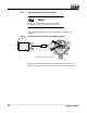
Step 1: Attach the HART modem to the computer Note If you do not have a HART modem or FIELDVUE digital valve controller available, proceed to Step 3. Attach the HART modem to the serial port (COM port) selected during installation. Step 2: Attach the HART modem to the FIELDVUE instrument Connect to PC Serial Port Modem E0350 / IL Figure 1-1. Instrument Connections Clip the HART modem leads to the FIELDVUE instrument TALK terminals.
Step 3: Start ValveLink Solo Figure 1-2. Starting ValveLink Solo Click the Start button. From the Start menu select Programs>ValveLink>ValveLink. Step 4: Log in Figure 1-3. Logging in as MANAGER. Log in to ValveLink Solo with the Default User Name and Password Default User Name: MANAGER Default Password: FALCON Click OK.
Note For full access to ValveLink Solo features you must discontinue use of the default name and password. Create security groups and assign new user names and passwords, then logout and login as a new user. Step 5: Add a New Security Group From the ValveLink Solo menu bar, select: Customize ValveLink>Security Groups.
Figure 1-4. Adding a New Security Group Click the Add New Group button. Figure 1-5. Naming the New Security Group Type a name for the new security group, then click the OK button.
Figure 1-6. Assigning Privileges to the New Security Group Select the privileges accessible to this group and click OK.
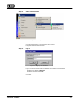
Step 6: Add a New User Account Figure 1-7. Selecting Users From the menu bar, select: Customize ValveLink>Users. Figure 1-8. Adding a New User Click the Add New User button.
Figure 1-9. Entering the New User Name and Password Type in a user name and password. Then type the password again to verify it. Click OK. Figure 1-10. Assigning a Security Group to the New User Click on the new user name to highlight it. Click the list box arrow to the right of the Security Group box and select the desired security group. Click OK.
Step 7: Log Out Figure 1-11. Selecting Exit/Log Out From the ValveLink Solo menu bar, select: Tag>Exit/Log Out. Figure 1-12. Logging Out Click the Log Out button.
Step 8: Log In as a New User Figure 1-13. Logging In Click the ValveLink Solo Log In button. Figure 1-14. Logging in as New User Enter your user name and password. Click OK.
Step 9: Double click on the valve symbol to open the Status diagnostic CLICK TO CLOSE WINDOW AND EXIT VALVELINK SOLO CLICK TO RESTORE TITLE BAR CLICK TO MINIMIZE MODEM SYMBOL VALVE SYMBOL Figure 1-15. Device Connection View Showing Connected Devices When ValveLink Solo starts up, it displays the connected devices in the left pane of the window (Device Connection View). Double click on the valve symbol to open the Status Diagnostic.
Step 10: Click the Start Monitoring button to begin monitoring instrument and valve parameters TITLE BAR DISPLAYS INSTRUMENT TAG STATUS BAR DISPLAYS TAG INFORMATION Figure 1-16.
Section 2 Quick Start for ValveLink Solo for FOUNDATION fieldbus Instruments2 This section contains quick start information for ValveLink Solo connected to a single FOUNDATION fieldbus instrument. For more information about connecting to a single instrument, or for information about connecting to an H1 segment, see the ValveLink software Installation Guide. For more information on using ValveLink Solo see ValveLink software help.
Step 1: Connect the computer to a FOUNDATION fieldbus digital valve controller Figure 2-1 shows how to connect to a single instrument with a fieldbus power hub (Relcom part number FCS-PH-110-PL, or equivalent). The power hub provides a power supply and double terminator. Up to four devices can be connected to the Relcom power hub. The computer with ValveLink Solo and the NI-FBUS interface card is considered as one device. This product is used for bench testing. It is not designed for field applications.
Step 2: Start ValveLink Solo Figure 2-2. Starting ValveLink Solo Click the Start button. From the Start menu select: Programs>ValveLink>ValveLink. When you start ValveLink Solo it will automatically start National Instruments Fieldbus (NI-FBUS) software if installed. If ValveLink Solo is shutdown without properly exiting the software, NI-FBUS will continue to run. So, before starting ValveLink Solo be sure NI-FBUS software is shut down. ValveLink Solo will not start if NI-FBUS software is running.
Step 3: Log in Figure 2-4. Logging in as MANAGER Login to ValveLink Solo with the Default User Name and Password: Default User Name: MANAGER Default Password: FALCON Click OK. Figure 2-5. ValveLink Solo NI-FBUS Startup Window ValveLink Solo starts the NI-FBUS software. As NI-FBUS software initializes, the startup window, shown in figure 2-5, appears. Do not stop the initializing process so that ValveLink Solo may start up successfully.
Figure 2-6. ValveLink Link Master Starting Window If you are not connected to a segment where a Link Active Scheduler is running, ValveLink Solo starts the Communications Manager in the LAS mode as indicated in the window shown in figure 2-6. Step 4: Click OK to continue the initializing process. After ValveLink Link Master Starting window disappears, the NI-FBUS startup window again appears temporarily to complete the initializing process.
Note The Link Active Scheduler (LAS) controls traffic on the H1 segment. For an active H1 segment, the LAS function is provided by the host system or another FOUNDATION fieldbus device. When ValveLink Solo is connected (to either an active segment or a single instrument), the NI-FBUS interface card waits to see if the LAS is present. If not, the NI-FBUS interface card provides the LAS function.
Note For full access to ValveLink Solo features you must discontinue use of the default name and password. Create security groups and assign new user names and passwords, then logout and login as a new user. Step 5: Add a New Security Group Figure 2-8. New Security Group From the ValveLink Solo menu bar, select: Customize ValveLink>Security Groups.
Figure 2-9. Security Groups Window Click the Add New Group button. Figure 2-10. Add New Group Window Type a name for the new security group, then click the OK button.
Figure 2-11. Security Groups Window Select the privileges accessible to this group and click OK.
Step 6: Add a New User Account Figure 2-12. Add New User From the menu bar, select Customize ValveLink>Users. Figure 2-13. Users Window Click the Add New User button.
Figure 2-14. Add New User Window Type in a user name and password. Then type the password again to verify it. Click OK. Figure 2-15. Selecting Security Group Click on the New User name to highlight it. Click the list box arrow to the right of the Security Group box and select the desired security group. Click OK.
Step 7: Log Out Figure 2-16. Log Out From the ValveLink Solo menu bar, select: Tag > Exit / Log Out. Figure 2-17. Exit ValveLink Click the Exit button to exit ValveLink software.
Step 8: Restart ValveLink Software and Log In as a New User Figure 2-18. Logging In Click the Log In button. Figure 2-19. OK for Login Button Enter your user name and password. Click OK. Step 9: After NI-FBUS completes start up, double click the instrument icon to open its tag for the status monitor. If a appears over the instrument symbol ValveLink Solo is not connected to the instrument. A possible reason for not connecting may be that the instrument is at a temporary address.
Figure 2-20. Digital Valve Controller at a Temporary Address. Click Change Address to change the Device Tag and Address Figure 2-21. Changing the Device Address preferred. However, if you are connected to an H1 segment, address 35 may be in use by another device. Select an unused address between 21 and 35. Click Set Address then click the Change Address button to assign the new address.
Figure 2-22. Reminder of Instrument Address Change changes, click the Done button. The instrument should be connected and you may proceed with instrument startup, calibration, and diagnostics. When you attempt to log out or exit ValveLink Solo, if the instrument was at a temporary address when you started, the message shown in figure 2-22 appears. You may leave the instrument at the set address or allow it to return to the temporary address.
Step 10: Click the Start Monitoring button to begin monitoring instrument and valve parameters TITLE BAR DISPLAYS INSTRUMENT TAG INSTRUMENT SYMBOL CHANGES TO VALVE SYMBOL STATUS BAR DISPLAYS TAG INFORMATION Figure 2-23.
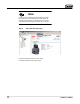
Section 3 Quick Start for AMS ValveLink SNAP-ON3 This section contains quick start information for AMS ValveLink SNAP-ON. For more information on using AMS ValveLink SNAP-ON see ValveLink software help. Section 7 of this document provides information on ValveLink software help. For more information on using AMS Suite: Intelligent Device Manager, see the associated help. Note This section assumes AMS Device Manager and AMS ValveLink SNAP-ON are installed.
CAUTION Do not run ValveLink Solo at the same time you are using AMS Device Manager or AMS Device Manager with AMS ValveLink SNAP-ON. Note To successfully use AMS ValveLink SNAP-ON, you must be familiar with using AMS Device Manager. Step 1: Start AMS Figure 3-1. Enter the AMS System Click a desktop icon or select AMS Device Manager from the Programs>AMS menu.
Figure 3-2. Login to the AMS System In the AMS User Login window, enter the correct Username and Password. Click OK to continue. Continue on with Step 3 to select a HART device. Go to Step 5 to select a fieldbus device.
Step 3: Select a HART device Communication Devices Figure 3-3. AMS Device Connection View (HART Device) In the Device Connection View window, right click the communication devices (modem, multiplexer) icon and select Scan All Devices.
Step 4: Start AMS ValveLink SNAP-ON Figure 3-4. Starting AMS ValveLink SNAP-ON (HART Device) Right click the instrument icon and select ValveLink from the context menu.
Step 5: Select a fieldbus device Figure 3-5. Starting AMS ValveLink SNAP-ON (fieldbus Device) In the Device View Connection window, right click the instrument icon and select SNAP-ON/Linked Apps > ValveLink from the context menu as shown in figure 3-5.
Section 4 Quick Start for ValveLink DTM 42 This section contains quick start information for ValveLink DTM. For more information on using ValveLink DTM see ValveLink software help. Section 7 of this document provides information on ValveLink software help. Note This section assumes ValveLink DTM is installed. The ValveLink Software Installation Guide, found on the ValveLink software installation CD, provides detailed installation information.
Note To successfully use the ValveLink DTM, you must be familiar with using the FDT frame application used to launch the ValveLink DTM. The information found in this section covers one example. Refer to the users guide for the FDT frame application that the ValveLink DTM is installed with for additional information. Step 1: Start the FDT frame application. Step 2: Select Add Device, as shown in figure 4-1, and click on the appropriate CommDTM. Select OK. Add Device Figure 4-1.
Step 3: With the CommDTM highlighted, select Add Device, as shown in figure 4-2, and click on the appropriate Device DTM. Select OK. Add Device Figure 4-2. Select the DeviceDTM Step 4: Set the appropriate settings for the CommDTM and DeviceDTM (see figure 4-3 and 4-4). Figure 4-3.
Figure 4-4. Setting the DeviceDTM Step 5: With the DeviceDTM highlighted, select Connect as shown in figure 4-5. Connect Figure 4-5.
Step 6: Once connected, select ValveLink DTM as shown in figure 4-6. Right Click on the Device Type and Select Additional functions to Access ValveLink DTM Figure 4-6.
Step 7: The ValveLink DTM will launch in a new window. All devices currently connected in the FDT frame application will show in the tree menu to the left of the ValveLink DTM window, as shown in figure 4-7. Double-click the device to open the device tag. Double-Click to open the device tag Figure 4-7.
Section 5 Quick Start for ValveLink PLUG-IN for PRM 53 This section contains quick start information for ValveLink PLUG-IN for PRM. For more information on using ValveLink PLUG-IN for PRM, see ValveLink software help. Section 7 of this document provides information on ValveLink software help. Note This section assumes ValveLink PLUG-IN for PRM is installed. The ValveLink Software Installation Guide, found on the ValveLink software installation CD, provides detailed installation information.
Note To successfully use ValveLink PLUG-IN for PRM, you must be familiar with using PRM software. Step 1: Run the PRM application. Step 2: Select a Fisher fieldbus digital valve controller from the PRM system. Step 3: Click on the PLUG-IN tab. Move the mouse cursor to the white list box, as shown in figure 5-1 and right-click. Select the Insert Control + Ins option. PLUG-IN Tab Insert Ctrl + Ins Figure 5-1.
Step 4: Select ValveLink PLUG-IN Launcher from the Tool Name dialog box and click on the OK button. Figure 5-2.
Step 5: Select ValveLink PLUG-IN Launcher and click on execute to start ValveLink PLUG-IN for PRM. Figure 5-3.
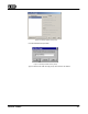
Section 6 ValveLink Software Buttons and Icons 64 This section describes the buttons and icons available on the ValveLink software toolbar and tree views. Tool Bar Buttons Toolbar buttons are shortcuts to ValveLink software commands. Tag Button—Opens the Tag Management window for locating a specific tag. From the Tag Management window you can open, modify, copy, or delete a selected tag. You can also print a report containing information from the listed tags.
Network Scan Button—Opens the Network Alert Scan window and allows you to scan selected tags. Using the Setup button you can select which tags to scan and which alerts to scan for. Network Scan is only available on ValveLink software setup to communicate through HART multiplexers. Instrument Mode Button—For DVC5000, DVC6000, DVC2000, and DVC6200 instruments, allows changing the instrument mode between In Service and Out of Service.
Calibration Button—Opens the Auto Travel Calibration window for the open tag. Available only on software with calibration enabled. See the ValveLink software Help screen, About ValveLink, to see if calibration is enabled. Instrument Status Button—Displays the Instrument Status window for the open tag. Provides device monitor, alert, and device information for an open tag. Step Response Button—Opens the Step Response window for the open tag.
Trending Button—For DVC5000, DVC6000, DVC2000, and DVC6200f instruments only. Displays operating parameter trends as they occur (live data), a parameter trend history (trend archive), and a valve travel histogram. Trend is set up from the Network Alert Scan window. Available only on software with trending enabled. See the ValveLink software Help screen, About ValveLink, to see if trending is enabled. Partial Stroke Ramp—For DVC6000 SIS and ODV instruments and DVC6200 ODV instruments.
Treeview Icons Valve icons on the device tree indicate the instrument service mode of the associated physical device. There are three modes which are reflected in the treeview icons. Travel Control, Pressure Control and SIS. If the instrument is in Travel Control, all icons associated with it will be green. Pressure Control is indicated by blue icons, and SIS is indicated by orange icons. The following treeview icons are seen in each of the control modes.
Out of Service—A bold yellow-on-black X over the lower right portion of the valve image indicates that the device is out of service. Communications Problem—A red X over the lower right portion of the valve image indicates that an error has occurred during the last communication attempt with the device. Check the communications log and troubleshoot the problem.
Section 7 ValveLink Software Help7 This section describes ValveLink software help. The help system provides step-by-step procedures for working with ValveLink software features. For every ValveLink software window, the help system defines edit fields, parameters, and buttons. The Glossary provides quick pop-up definitions.
Accessing Help To access help you can: Click the Help button on any window, Figure 7-1.
select an option from the Help menu, Figure 7-2. Help Options or press F1.
Using the Glossary When you need a quick definition of a term, an edit field, or instrument parameter, use the Glossary. Step 1: Access ValveLink help by selecting Contents from the Help menu Figure 7-3.
Step 2: Click Glossary button in the Contents tab Step 3: Click an alphabetic button to narrow your search Figure 7-4.
Finding Help Topics For detailed information about a particular topic, you can: Select a Topic from the Help Contents The Contents are similar to the table of contents in a paper manual. Find an entry that interests you then click its title. Figure 7-5.
For information, contact your local Emerson Process Management sales office or local business partner. Visit www.Fisher.