Precision Cooling For Business-Critical Continuity Liebert Process Fluid Chiller™ Technical Data Manual - 1.
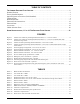
TABLE OF CONTENTS THE LIEBERT PROCESS FLUID CHILLER . . . . . . . . . . . . . . . . . . . . . . . . . . . . . . . . . . . . . . . . . . 1 Standard Features . . . . . . . . . . . . . . . . . . . . . . . . . . . . . . . . . . . . . . . . . . . . . . . . . . . . . . . . . . . . . . . . . 2 Factory-Installed Options . . . . . . . . . . . . . . . . . . . . . . . . . . . . . . . . . . . . . . . . . . . . . . . . . . . . . . . . . . . 2 Optional System Accessories (Field-Installed). . . . . . . . . . . . . . . . .
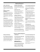
THE LIEBERT PROCESS FLUID CHILLER In addition, the Process Fluid Chiller is easy to install, requiring only final piping and wiring connections for proper operation. Water cooled electronic equipment has special needs beyond cool water. Sensitive equipment requires year-round operation, precise temperature-regulated water flow and a clean circulating loop—features only available with an equipmentmatched, dedicated chiller. For best reliability, this chiller should be factory-tested and supported.
Standard Features Frame and Panels Refrigerant Dehydrator The unit base is heavy-gauge galvanized steel. The exterior panels are painted and provide a durable, weather-resistant finish. The refrigerant dehydrator assures a moisture-free refrigerant system for extended component life. Indoor or Outdoor Installation The weatherproof panels and rugged components are durable for placement outdoors. Circulating fluid may be specified with propylene or ethylene glycol to adapt the unit to cold climates.
Optional System Accessories (Field-Installed) Fluid Pressure Gauge Isolation Ball Valve A 2 ½ inch (6.35 cm) analog gauge for monitoring supply or return pressure is available. The readout is dual scale: 0 to 100 PSI and 0 to 7 BAR. An available brass, ¼ turn isolation valve provides for isolation of fluid piping components in the event of a service necessity. Dial Thermometer To provide supply or return fluid temperature measurement, a hermetically sealed dial thermometer is available.
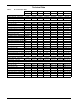
Technical Data Table 2 Air-cooled data—60Hz PS018A PS024A PS036A PS048A PS060A PS096A PS120A 1.5 Tons 2 Tons 3 Tons 4 Tons 5 Tons 8 Tons 10 Tons Circulating Fluid—Water Coolant Flow Rate - GPM (L/M) 2.4 (9) 3.3 (12.6) 5.9 (40.7) 11.1 (76.8) Pressure Drop - PSI (kPa) Net Cooling Capacity—BTUH (kW) 5.3 (19.8) 7.9 (29.4) 10.2 (38.4) 16 (60.6) 20 (75.8) 5.1 (35.0) 8.1 (55.6) 13.3 (91.8) 8.1 (55.8) 13.2 (91.0) 45°F (7.2°C) LWT 11800 (3.5) 17000 (5.0) 26600 (7.8) 39300(11.5) 51200 (15.
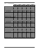
Table 3 Air-cooled data—50Hz PS021A PS028A PS038A PS047A PS059A 1.5 Tons 2 Tons 3 Tons 4 Tons 5 Tons Coolant Flow Rate - GPM (L/M) 2.5 (9.6) 3.7 (13.8) 5.1 (19.2) 7.9 (30.0) 8.3 (31.2) Pressure Drop - PSI (kPa) 6.1 (42.1) 12.3 (84.6) 4.9 (33.5) 8.1 (55.6) 10.2 (70.2) 45°F (7.2°C) LWT 12500 (3.7) 18300 (5.4) 25400 (7.4) 39800 (11.7) 41400 (12.1) 50°F (10.0°C) LWT 14000 (4.1) 20900 (6.1) 28100 (8.2) 43300 (12.7) 46700 (13.7) 55°F (12.8°C) LWT 15400 (4.5) 23400 (6.
Dimensional Data Figure 1 Cabinet size and floor planning dimensional data, 1.5 - 5 ton air cooled A AIRFLOW IN B D AIRFLOW OUT C* SHADED AREAS INDICATE A RECOMMENDED CLEARANCE FOR COMPONENT REMOVAL, ACCESS, AND AIR FLOW. OPTIONAL REFRIGERANT PRESSURE GAUGES 2" 18" (457mm) (51mm) SHADED AREAS INDICATE A RECOMMENDED CLEARANCE FOR COMPONENT REMOVAL, ACCESS, AND AIR FLOW. 36" (914mm) 36" (914mm) I I H 1" MAX. (25mm) H 1" NPT FEMALE TYPICAL ON MODELS G PS036A, PS048A & PS060A 36" (914mm) 1" MAX.
Figure 2 Cabinet size and floor planning dimensional data, 1.5 - 5 ton air-cooled models with thermal storage tank A B C D AIRFLOW IN C* STANDARD PS048A AIRFLOW OUT OPTIONAL REFRIGERANT PRESSURE GAUGES C E C FACTORY ASSEMBLED STORAGE TANK CABINET (SEE NOTE 1 ) 30" C C 18" (457mm) SHADED AREAS INDICATE A RECOMMENDED CLEARANCE FOR COMPONENT REMOVAL, ACCESS, AND AIR FLOW.
Figure 3 Cabinet and floor planning dimensional data, 8-10 ton air cooled Table 4 Model Numbers 60 Hz PS096A PS120A 8 Dimensional data, 8-10 ton air-cooled A B C D Module Weight (empty) lbs. (kg.
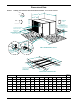
Figure 4 Cabinet and floor planning dimensional data, 8-10 ton air cooled with thermal storage tank cabinet Table 5 Dimensional data, 8-10 ton air-cooled models with thermal storage tank cabinet Model Numbers 60 Hz PS096A PS120A Dimensional Data in (mm) A B C D E 77 (1956) 39-1/4 (997) 38-1/2 (978) 5-1/2 (140) 69-1/4 (1759) Module Weight (empty*) lbs (kg) Storage Tank Capacity gal (L) 1170 (531) 100 (380) * Note: Add weight of fluid for operating weight 9
10 SL-11601 PG 5 Cold Water Supply Warm Water Return Schrader Valve Optional Reservoir Heater Sight Glass Optional Fluid Relief Valve Fluid Relief Valve Low Fluid Temperature Control Evaporator External Equalizers Optional High Temperature Thermostat Cold Water Supply Optional Fluid Pressure Gauges Warm Water Return FIELD PIPING FACTORY PIPING SINGLE CIRCUIT SHOWN Lee-Temp Receiver Pressure Balancing Valve Check Valve 1/2" (12.
SL-11601 PG 5A Cold Water Supply Isolation Ball Valves Optional High Temperature Thermostat Solenoid Valve Cold Water Supply Optional Fluid Pressure Gauges Warm Water Return Expansion Valve Hot Gas Bypass Optional Isolation Optional Ball Valves Low Flow Switch Low Fluid Temperature Control Evaporator High Pressure Switch Filter Drier Check Valve FIELD PIPING FACTORY PIPING Heater Lee-Temp Receiver Pressure Balancing Valve Check Valve Pressure Relief Valve Condenser Coil Head Pressure
Electrical Field Connections Figure 7 Electrical field connections, 1.5 - 5 ton air cooled Field supplied unit disconnect switch recommended within sight of unit. Single or three phase electrical service not by Liebert. Optional field supplied 24V NEC Class 2 control wiring. Factory wired to components on electrical panels. High pressure switch reset button. Line voltage connection block. High voltage electric power supply entrance. Remote Unit Shutdown 37 & 38.
Figure 8 Electrical field connections, 8-10 ton air cooled ! WARNING Potentially lethal voltages exist within this equipment during operation. Observe all cautions and warnings on unit and in this manual. Failure to do so could result in serious injury or death. Only qualified service and maintenance personnel should work with this equipment.
Electrical Data Table 6 Electrical data—60Hz Stainless Steel Pump (Standard) With Heater Tons Without Heater Model Voltage FLA WSA OPD FLA WSA OPD 1-1/2 PS018A 208/230, 1 Phase 16.7 19.1 25 15.7 18.1 25 2 PS024A 208/230, 1 Phase 18.0 20.7 30 17.0 19.7 30 PS036A 208/230, 1 Phase 22.6 26.5 40 21.7 25.6 40 PS036A 208/230, 3 Phase 15.9 18.6 25 14.9 17.6 25 3 4 5 8 10 Table 7 PS036A 460, 3 Phase 8.6 10.1 15 8.0 9.5 15 PS048A 208/230, 3 Phase 21.1 24.
Figure 9 Process chiller pump performance—60Hz 300 2 hp (multistage) 250 Total Head - Ft 200 150 3 hp (single stage) 100 1 hp (single stage) 50 3/4 hp (single stage) 0 0 10 20 30 40 50 60 Flow Rate - GPM 15
Accessories Figure 10 Emergency water switchover—optional Power switch Power Switch Toggle switch Toggle Switch Push Pushbutton Button Temperature display Temperature Display Copper Copper Piping piping Temperature Temperature set point button Set Poin t Button Valve handle Valve Handle Pressure gauge Pressu re Gauge 36" 36.00 18" 22.5" 6" 6" 6" 4.5" 1.25" 33" .00 3" 8" 8" 4.5" 4.50 8" 33" .00 112" 2.00 330" 0.
Figure 11 Wall-mounted monitoring box—optional Flow meter Flow M eter Pressure Pressure Gauges gauges 36" 36.00 18" 22.5" Pressure Pressure Gauges gauges 4.5" 1.25" 3" Piping Piping Cconnections onnections 8" 8" PPiping iping Connections 18" connections 4.5" 3" 3.00 8" 12" 12.00 30" 30.
Figure 13 Water level control module—optional Piping connections Piping Connections Power switch Pow er Switch 8.0" 2.0" 2.8" 8.0" Wiring Wiringconnections Connections 8.0" 12.0" 12.00 3.92" 3.923.06" 3.06 2.0" 2.00 3.38" 3.38 8.0" 30.0" 30.00 RIGHT RIGHT 12.0" 12.00 LEFT LEFT REAR REAR 12" 12.0" Shaded areas indicate a recommended clearance SHADEDAREASINDIC ATEA for component RECOMMENDEDCremoval LEARANCE and F access ORCOMPONENT REMOVAL ANDACCESS. 24" 24.0" 24.0" 24" 36.
Figure 14 Typical piping arrangement using optional emergency water switchover and water level control ter Ra yTEW itA W C CITY ler eroll t v n oe erl LC er Letve troll a r e tW n Wa Co ce your rcS n e e e t ga urc rW e o y c n er S gem rE t Eme Wa D LOA ad Lo Drain DRAIN sr esille osscChller r Pe i roc Ch P INIndoor DOOR(Water-Only) (WATER-ONApplication LY) APPLICATION Water Feed Water Feed to to Evaporator Evaporator Inlet Line Inlet Line 19
CHILLER SELECTION FORM Gathering and providing the information on this form will help determine the chiller and options needed to provide satisfactory performance. Fill out the form and send to a local Liebert representative.
GUIDE SPECIFICATIONS, 1.5 TO 10 TON PROCESS FLUID CHILLER 1.0 GENERAL 1.1 Summary These specifications describe requirements for a self-contained air-cooled process fluid chiller system. 1.2 Design Requirements The chiller shall be a Liebert model______, self-contained aircooled chiller system. Each system shall have a net cooling capacity of______BTU/HR (kW), based on a leaving coolant fluid temperature of_____ °F (°C), and 95°F ambient air temperature.
3.3 Storage Tank System shall include a ____ gallon stainless-steel storage tank, factory piped, and installed beneath the chiller cabinet. 4.0 ACCESSORIES 4.1 Emergency Water Switchover Module This module shall automatically switch to emergency (city) water on either a high fluid temperature alarm or loss of fluid flow alarm.
Ensuring The High Availability 0f Mission-Critical Data And Applications. Emerson Network Power, the global leader in enabling business-critical continuity, ensures network resiliency and adaptability through a family of technologies—including Liebert power and cooling technologies—that protect and support business-critical systems. Liebert solutions employ an adaptive architecture that responds to changes in criticality, density and capacity.