Precision Cooling For Business-Critical Continuity™ Liebert® 10 Fan Drycooler/Fluid Cooler ™ Including Quiet-Line Models User Manual - 120 to 150 Tons, 50 & 60 Hz
TABLE OF CONTENTS IMPORTANT SAFETY INSTRUCTIONS . . . . . . . . . . . . . . . . . . . . . . . . . . . . . . . . INSIDE FRONT COVER 1.0 INTRODUCTION . . . . . . . . . . . . . . . . . . . . . . . . . . . . . . . . . . . . . . . . . . . . . . . . . . . . . . . . . .3 1.1 System Description and Standard Features . . . . . . . . . . . . . . . . . . . . . . . . . . . . . . . . . . . . . . . 3 1.2 Optional Features. . . . . . . . . . . . . . . . . . . . . . . . . . . . . . . . . . . . . . . . . . . . . . . .
FIGURES Figure 1 Figure 2 Figure 3 Figure 4 Figure 5 Figure 6 Figure 7 Figure 8 Figure 9 Figure 10 Figure 11 Figure 12 Typical application . . . . . . . . . . . . . . . . . . . . . . . . . . . . . . . . . . . . . . . . . . . . . . . . . . . . . . . . . . . . . . . 4 Capacity correction factor. . . . . . . . . . . . . . . . . . . . . . . . . . . . . . . . . . . . . . . . . . . . . . . . . . . . . . . . . . 7 Pressure drop correction factor . . . . . . . . . . . . . . . . . . . . . . . . . . . . . . . . . .
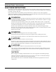
IMPORTANT SAFETY INSTRUCTIONS SAVE THESE INSTRUCTIONS This manual contains important safety instructions that should be followed during the installation and maintenance of the Liebert® 10 Fan Drycooler™. Read this manual thoroughly before attempting to install or operate this unit. Only properly trained and qualified personnel should move, install or service this equipment. Adhere to all warnings, cautions and installation, operating and safety instructions on the unit and in this manual.
NOTICE Risk of a leaking coil due to freezing and/or corrosion. Can cause equipment and building damage. Cooling coils and piping systems that are connected to open cooling towers or other open water/glycol systems are at high risk for freezing and premature corrosion. Fluids in these systems must contain the proper antifreeze and inhibitors to prevent freezing and premature coil corrosion.
Introduction 1.0 INTRODUCTION 1.1 System Description and Standard Features The Liebert® 10 Fan Drycooler/Fluid Cooler™ is designed for maximum heat rejection with minimum footprint and to be used with glycol solutions for large-site installations. It has a nominal range of 150 tons of heat rejection and is ideal for rejecting the heat of multiple evaporator units. Standard features include: • Three different coil circuits: 068 (half), 136 (full), 272 (double).
Introduction Figure 1 Typical application Refer to Figure 7 for a detailed installation diagram.
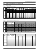
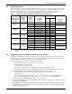
Product Performance Data & Selection 2.0 PRODUCT PERFORMANCE DATA & SELECTION 2.1 Standard Data Table 1 Drycooler performance data Total Heat Rejection* @25°F (13.9°C) ITD Model No. Hz 120 Btu/h 60 150 60 150 50 No. & No. & Size of Size of No. of Connec- Connec- No. Air Flow Ft of Internal tions tions of kW gpm lps Water kPa Circuits (inlet) (outlet) Fans cfm cmh Flow Rate 8.6 Pressure Drop Internal Shipping Sound Volume Weight dBA** Gal L Lbs Kg 1,172,000 343 136 27.2 81.2 68 2@2.
Product Performance Data & Selection 2.2 Typical Application The most popular use for the Liebert® 10 Fan Drycooler™ is at sites with large cooling loads, such as data center/telecom sites where multiple indoor air conditioners are used. See Table 4 for general outline of suggested quantity of indoor units for each Liebert 10 Fan Drycooler or contact your Emerson® representative for custom matchup. Figure 1 illustrates typical application.
Product Performance Data & Selection 6. Find the Flow Rate per Circuit, VC = VT / circuits for the drycooler selected in Table 2. This should be in the range of 1.0 to 2.0 gpm/circuit (0.06 to 0.13 lps/circuit) for proper long-term performance. 7. In Table 2, for the selected Model Number, find the Actual Heat Rejection per ITD using the gpm/circuit from Step 6. You may interpolate between columns as required.
Product Performance Data & Selection Pressure drop correction factor 1.15 Glycol Percentage and Fluid Temperature Glycol Percentage Figure 3 Correction Factor 1.10 1.05 1.0 0.95 50 40 0.90 30 20 0.55 10 0 0.80 °F 80 (°C) (26.7) 100 (37.8) 120 (48.9) 140 (60) 160 (71.
Product Performance Data & Selection 2.4 Selection Example For the following example, English (I-P) units will be used. Metric units are also provided in the tables and figures. Find a drycooler to cool 340 gpm of 20% ethylene glycol/water solution from 125°F to 115°F. Application is near sea level and has an outdoor design air temperature of 95°F. 1. Assume the following values: • Toa = 95°F • VT = 340 gpm • 20% ethylene glycol • Tef = 125°F • Tlf = 115°F 2.
Installation 3.0 INSTALLATION NOTE Follow all unit dimensional drawings carefully. Determine whether any building alterations are required to run piping and wiring. Also refer to the submittal engineering dimensional drawings. 3.1 Location Considerations The drycooler should be located for maximum security and maintenance accessibility. Avoid ground level sites with public access or areas which contribute to heavy snow or ice accumulations.
Installation Figure 4 Clearance considerations Wall 96" (2438mm) 96" (2438mm) 96" (2438mm) 72" (1829mm) Wall NOTES: 1. All dimensions are minimum, unless otherwise noted. 2. Pit installations are not recommended. Recirculation of hot discharge air in combination with surface air turbulence cannot be predicted. Hot air recirculation will severely affect unit efficiency and can cause high-pressure trips or fan motor temperature trips.
Installation 3.2 Site Preparation Drycoolers should be installed in a level position to assure proper venting and drainage. This space should have all services (electrical, drain, water) in close proximity. Also, the space should be level and free of loose gravel, sand, flooring or roofing. For roof installation, mount drycoolers on steel supports in accordance with local codes. To minimize sound and vibration transmission, mount steel supports across load-bearing walls.
Installation Table 8 3.3 Drycooler physical data Model # No. of Fans CFM (CMH) 60Hz. CFM (CMH) 50Hz. Coil Internal Vol. Gal (L) Net Weight Lb (kg) D*N*150**068 10 99030 (168250) 82450 (140080) 92.8 (351) 5100 (2313) D*N*150**136 10 99030 (168250) 82450 (140080) 92.8 (351) 5100 (2313) D*N*150**272 10 99030 (168250) 82450 (140080) 92.8 (351) 5100 (2313) DGN*120**068 10 74160 (126000) N/A 92.8 (351) 5100 (2313) DGN*120**136 10 74160 (126000) N/A 92.
Installation 3.4.1 Unit Weight Dry weight of the unit is 5100 lb. (2313kg). ! WARNING Risk of unit very heavy unit tipping over. Can cause equipment damage, personal injury and death. To avoid a tilt hazard, adjustment may be necessary to locate the center of gravity before lifting the unit.
Installation 3.5 Piping Connections See Figure 7 for a typical piping diagram. See Figure 8 piping locations. NOTICE Risk of overpressurization. Can cause equipment damage. To avoid the possibility of burst pipes, it is necessary to install a relief valve in the system. This valve may be obtained from your supplier as an option or may be sourced from another vendor. Galvanized pipe must not be used in glycol systems.
Installation Figure 7 Typical piping diagram 16
Installation Figure 8 Piping dimensions NOTE Tolerance of ±1" (25.4mm) on all piping dimensions B A 68-5/8" (1743mm) Outlet Typ. 50-3/16" (1275mm) Inlet Typ. 14-1/2" (369mm) Outlet B A 22" (559mm) Inlet 63-1/2" (1613mm) Intlet 71-7/8" (1825mm) Outlet Table 9 DPN000986 REV. 0 Piping, drycoolers Connection Sizes (ODS) Model #. No. Fans No. of Internal Circuits D*N*150**068 10 68 2 2 2.625" (66.7mm) 2.625" (66.7mm) D*N*150**136 10 136 2 2 4.125'' (104.8mm) 4.125'' (104.
Installation Table 10 Piping specifications Model No. of Internal Circuits D0N*150** 68 DTN*150** 136 DGN*120** 272 No. of Inlets (A) No. of Outlets (B) Connection Sizes, Inlet and Outlet OD (in.) * Coil Internal Volume, Gal. (l) 2.625 2 2 4.125 92.8 (351) *Cut off closed end of connection tube; connect couplings and elbows as required. Table 11 Volume in standard Type L copper piping Diameter (in.) Volume Outside Inside gal/ft l/m 1-3/8 1.265 0.065 0.81 1-5/8 1.505 0.
Installation NOTICE Risk of improper handling of glycol. Can cause environmental damage. When mishandled, glycol products pose a threat to the environment. Before using any glycol products, review the latest Material Safety Data Sheets and ensure that you can use the product safely. Glycol manufacturers request that the customer read, understand and comply with the information on the product packaging and in the current Material Safety Data Sheets.
Installation 3.6.3 Filling the System Emerson® recommends installing hose bibs at the lowest point of the system. When filling a glycol system, keep air to a minimum. Air in glycol turns to foam and is difficult and time-consuming to remove. (Anti-foam additives are available and may be considered.) Open all operating systems to the loop. With the top vent(s) open, fill the system from the bottom of the loop. This will allow the glycol to push the air out of the top of the system, minimizing trapped air.
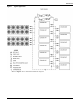
Installation Figure 9 Electrical field connections Remote Start Contact Remote Alarm Contacts On Loss of Current Control Fuse and Fuse Block Current-Sensing Relay Option High-Voltage Fuses and FuseBlocks Factory-Installed Disconnect Switch 70 71 80 81 83 84 85 86 101 102 103 104 105 Ground Lug Power Control Switch L1 L2 L3 Thermostat 1st and 2nd Stage and Display Modules Contactor Entrance Field-Supplied Low Voltage Class 2 Wiring 7/8" (22mm) Knockout Electric Service (not by (3 Places) Emerson®
Installation 3.7.2 Low Voltage Control Wiring A control interlock between the drycooler and the heat load(s) will require 24V Class 2 copper wiring for remote On/Off sequencing of the drycooler with the load. Refer to the electrical schematic for wiring to Terminals 70 & 71. See Figure 10 for typical low-volt system wiring. If the current sensing relay option is provided, 24V Class 2 wiring will be necessary to make the connections to monitor motor operation.
Installation 3.8 Checklist for Completing Installation NOTE After installation, proceed with the following list to verify that the installation is complete. Complete and return the Warranty Inspection Check Sheet which is shipped with the unit and return to the address indicated on the check sheet. ___ 1. Proper clearances for service access have been maintained around the equipment. ___ 2. Equipment is level and mounting fasteners are tight. ___ 3. Piping completed to coolant loop. ___ 4.
Operation 4.0 OPERATION ! WARNING Risk of electric shock. Can cause injury or death. Disconnect all local and remote electric power supplies before working within the unit. The fans may start unexpectedly. Disconnect the power supply before working on the unit. Line side of factory disconnect remains energized when the disconnect is Off. Use a voltmeter to make sure power is turned off before checking any electrical connections or functions. 4.1 Initial Startup Procedure Refer to 3.
Operation Figure 11 Fluid temperature controls 25
Operation 4.1.2 Current-Sensing Relays If supplied, be sure that the current-sensing relays (CSR) are wired as per the wiring schematic using 24V Class 2 copper wiring. When the thermostat closes, a 24-volt signal will be sent to the relevant terminals of the CSR. When this occurs, a time delay starts, allowing the amperage to be sensed on the load side of the contactors. First, set selection under amperage on selector switch, then start all fans. Set the trip delay for 50%.
System Maintenance 5.0 SYSTEM MAINTENANCE ! WARNING Risk of electric shock. Can cause injury or death. Disconnect all local and remote electric power supplies before working within the unit. The fans may start unexpectedly. Disconnect power supply before working on unit. Line side of factory disconnect remains energized when disconnect is off. Use a voltmeter to make sure power is turned off before checking any electrical connections or functions 5.
System Maintenance 5.2 Special Procedures 5.2.1 Drycooler Cleaning Keeping the outdoor drycooler coils clean is an important factor in maintaining peak efficiency, reliability and long life of the equipment. It is much easier to keep up on frequent cleanings rather than wait until heavy build up has occurred which may create head pressure problems with the evaporator units. When to Clean Normal conditions typically dictate cleaning twice a year, spring and fall.
System Maintenance 5.2.2 Maintenance Inspection Checklist Date:____________________________________ Prepared By:____________________________________ Model #:_________________________________ Serial Number:__________________________________ NOTE Regular inspections are necessary to assure proper cleanliness of the cooling fins. Should inspection reveal dirt or corrosion, appropriate cleaning should be performed. Monthly Drycooler Semiannually Drycooler ___ 1. Coil surfaces free of debris ___ 1.
Troubleshooting 6.
Ensuring The High Availability Of Mission-Critical Data And Applications. Emerson Network Power, a business of Emerson (NYSE:EMR), is the global leader in enabling Business-Critical Continuity™ from grid to chip for telecommunication networks, data centers, health care and industrial facilities.