FM-3 Programming Module Installation Manual P/N 400508-02 Revision: A2 Date: August 23, 2000 © EMERSON Motion Control, Inc.
FM-3 Programming Module Installation Manual Information furnished by EMERSON Motion Control is believed to be accurate and reliable. However, no responsibility is assumed by EMERSON Motion Control for its use. EMERSON Motion Control reserves the right to change the design or operation of the equipment described herein and any associated motion products without notice. EMERSON Motion Control also assumes no responsibility for any errors that may appear in this document.
© EMERSON Motion Control, Inc. 2000 Part Number: 400508-02 Revision: A2 Date: August 2000 Printed in United States of America Information in this document is subject to change without notice. Companies, names, and data used in examples herein are fictitious unless otherwise noted. No part of this document may be reproduced or transmitted in any form or by any means, electronic or mechanical, for any purpose, without the express written permission of EMERSON Motion Control.
Customer Service It is EMERSON Motion Control’s goal to ensure your greatest possible satisfaction with the operation of our products. We are dedicated to providing fast, friendly, and accurate assistance. That is why we offer you so many ways to get the support you need. Whether by phone, fax or modem, you can access EMERSON Motion Control support information 24 hours a day, seven days a week. EMERSON Motion Control 12005 Technology Drive Eden Prairie, Minnesota 55344 U.S.A.
Need on-site help? EMERSON Motion Control provides service, in most cases, the next day. Just call EMERSON’s customer service center when on-site service or maintenance is required. Training Services (800)397-3786 or Fax (952)995-8011 EMERSON Motion Control maintains a highly trained staff of instructors to familiarize customers with EMERSON Motion Control’s products and their applications. A number of courses are offered, many of which can be taught in your plant upon request.
Document Conventions Manual conventions have been established to help you learn to use this manual quickly and easily. As much as possible, these conventions correspond to those found in other Microsoft® Windows®1 documentation. Menu names and options are printed in bold type: the File menu. Dialog box names begin with uppercase letters: the Axis Limits dialog box. Dialog box field names are in quotes: “Field Name”. Button names are in italic: OK button. Source code is printed in Courier font: Case ERMS.
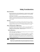
Safety Instructions General Warning Failure to follow safe installation guidelines can cause death or serious injury. The voltages used in the product can cause severe electric shock and/or burns, and could be lethal. Extreme care is necessary at all times when working with or adjacent to it. The installation must comply with all relevant safety legislation in the country of use.
Safety Considerations Safety Precautions This product is intended for professional integration into a complete system. If you install the product incorrectly, it may present a safety hazard. The product and system may use high voltages and currents, carry a high level of stored electrical energy, or control mechanical equipment that can cause injury.
relevant safety legislation in the country of use. AC supply isolation device The AC supply must be removed from the drive using an approved isolation device or disconnect before any servicing work is performed, other than adjustments to the settings or parameters specified in the manual. The drive contains capacitors which remain charged to a potentially lethal voltage after the supply has been removed.
Table of Contents Customer Service. . . . . . . . . . . . . . . . . . . . . . . . . . . . . . . . . . . . . . . . . . . . . . . . . . . . . . . . . . . . . iii Reference Materials . . . . . . . . . . . . . . . . . . . . . . . . . . . . . . . . . . . . . . . . . . . . . . . . . . . . . . . . . . . vi Safety Considerations . . . . . . . . . . . . . . . . . . . . . . . . . . . . . . . . . . . . . . . . . . . . . . . . . . . . . . . . . vii Introduction 1 Installation 3 Basic Installation Notes . . . . . .
x
FM-3 Programming Module Installation Manual Introduction FM-3 is a compact and rugged function module that attaches to the front of the E Series drive. It provides eight digital input lines and four digital output lines, in addition to the four input and three output lines available on the E Series EN drive. Unlike other function modules, the FM-3 offers complex motion profiling.
FM-3 Programming Module Installation Manual The FM-3 stores E Series drive setup parameters within the module itself. This allows you to transfer the FM-3 to another E Series drive without losing setup parameters. Fastening Latch 3 Row by 12 Character Display Soft Keys Direction Arrow Keys Programming Module 100-Pin Connector 1 2 3 Inputs 4 5 Inputs 6 7 485 - 8 SHLD 1 Outputs Sync. Input Sync. Intput Exp. I/O Expanded I/O 485 + 2 3 Outputs 4 10-30 VDC Sync. Output Sync.
FM-3 Programming Module Installation Manual Installation Basic Installation Notes You are required to follow all safety precautions during start-up such as providing proper equipment grounding, correctly fused power and an effective Emergency Stop circuit which can immediately remove power in the case of a malfunction. See the “Safety Considerations” section for more information. Mechanical Installation The FM-3 detects and verifies the drive serial number when its attached to an E Series drive.
FM-3 Programming Module Installation Manual Press down on the latch located on the top of the FM. 2 Gently pull the FM away from the drive. A slight rocking motion may be used to loosen the FM's connector. 3 Grip the FM 1 on each side of the LCD. 4 Continue pulling the top of the FM away from the drive until the connector clears the drive. Lift the FM out of the aligning tab slot and away from the drive.
Installation Software Installation Emerson Motion Control PowerTools® FM-3 software was designed for users who need access to all setup options and diagnostic information for the drive. The software provides access to all commonly used drive parameters. PC System Configuration Required: • Microsoft® Windows® 95/98 or Microsoft Windows NT® 4.0 (service pack 3) • Serial port • Mouse • 3.
FM-3 Programming Module Installation Manual 3. In the Run dialog box, type a:/setup, where a is the letter assigned to your 3.5" floppy drive. 4. Click the OK button, then follow the instructions on your screen. Installation will take about five minutes. The install program automatically: • Creates the directory on your hard drive named: C:\EMERSON\PT-FM3 • Creates a new Windows group called "EMERSON Motion Control-FM3". • Loads the required DLL’s into your Windows system directory.
Installation Exiting the Software Choose File from the menubar, then click Exit. If you are using the keyboard, press the shortcut key combination Alt+F, X. If you made changes, PowerTools displays an Alert dialog box asking whether you want to save your current work. Click the Yes button or press Enter to save your work, or click the No button to quit without saving. Accessing Help All PowerTools tabs and dialog boxes provide a Help button.
FM-3 Programming Module Installation Manual 8
FM-3 Programming Module Installation Manual Diagnostics and Troubleshooting Diagnostic Display The diagnostic segment display on the front of the drive shows drive status, FM-3 status, and fault codes. When a fault condition occurs, the drive will display the fault code, overriding the status code. The alphanumeric display on the FM-3 provides additional fault information. The decimal point is “On” when the drive is enabled, and the stop input is not active.
FM-3 Programming Module Installation Manual Display Indication Status Description FM-3 Keypad Display Jog is executing. Drive Type Motor Type Menu Groups Address Jogging Program is executing. Drive Type Motor Type Menu Groups Address Program Fault Codes A number of diagnostic and fault detection circuits are incorporated to protect the drive.
Diagnostics and Troubleshooting Segment Display Fault Action to Reset Bridge Disabled FM-3 Display Invalid Configuration Button or Input Yes Invalid Conf Power Module Button or Input Yes Power Module High DC Bus Button or Input Yes High DC Bus Low DC Bus Button or Input Yes Low DCBus Encoder State Power Yes Encoder State Encoder Hardware Power Yes Encoder HW Motor Overtemp Button or Input Yes MotorOvrTemp RMS Shunt Power Button or Input Yes RMS ShuntPowr Overspeed Butto
FM-3 Programming Module Installation Manual Segment Display Fault Action to Reset Normally on for one second during power up All "On" Bridge Disabled FM-3 Display Yes ** Fault ** ***** Depend on Fault FM-3 Fault Descriptions Flash Invalid This fault indicates that the firmware checksum has failed. Use the Tools Program Flash menu item from Emerson Motion Control PowerTools® to reprogram/upgrade the firmware stored in flash memory. If this problem persists, call EMERSON Motion Control.
Diagnostics and Troubleshooting Invalid Configuration The FM was not on this drive during its previous power-up and it is not known if the setup data in the FM matches the drive and motor to which the FM is now attached. This can also happen when a FM is removed from a drive and the drive is powered-up. To reset the fault, create or open a configuration file with the correct drive and motor selections and download the configuration to the FM or drive.
FM-3 Programming Module Installation Manual Encoder Hardware If any pair of encoder lines are in the same state, an encoder line fault is generated. The most likely cause is a missing or bad encoder connection. Motor Overtemp This fault is generated when the motor thermal switch is open due to motor over-temperature or incorrect wiring. RMS Shunt Power This fault is generated when RMS shunt power dissipation is greater than the design rating of the internal shunt.
Diagnostics and Troubleshooting FM-3 Specific Fault Descriptions Figure 5: EN - 2 0 4 MG - 3 1 6 ADR 0 1 S EC UR QU I CK FM-3 display is used to display drive and FM-3 faults Traj Fault This fault occurs when the drive has received trajectory data from the FM-3 that indicates a problem. Check the user units, velocities, accels and decels for correct values. ISR Overrun This fault is generated when a module flash memory problem occurs. To correct, replace the FM-3.
FM-3 Programming Module Installation Manual Brake Operation MG motor brake operation is controlled by the Brake Release and Brake Control destinations. These destinations can be used together to control the state of the Brake source. The table below shows the relationship between the Brake sources and destinations (see “Diagnostic Display”). Note No motion should be commanded while the brake is engaged.
Diagnostics and Troubleshooting Analog Outputs The drive has two 10 bit Analog Outputs which may be used for diagnostics, monitoring or control purposes. These outputs are referred to as Channel 1 and Channel 2. They can be accessed from the command connector on the drive or from the diagnostics output pins located on the front of the drive. Each Channel provides a programmable Analog Output Source. (In early releases, the FM-3 analog output is fixed at the default selections.
FM-3 Programming Module Installation Manual Diagnostic Analog Output Test Points The DGNE cable was designed to be use with either an oscilloscope or a meter. The wires are different lengths to avoid shorting to each other. However, if signals do get shorted to GND, the drive will not be damaged because the circuitry is protected.
Diagnostics and Troubleshooting D/A Black (GND) D/A Yellow Blue 10 Ohm 10 Ohm DGNE Cable DGNE Cable Figure 7: Command Connector (J5) Diagnostic Cable (DGNE) Diagram 19
FM-3 Programming Module Installation Manual Drive Faults The Active Drive Faults dialog box is automatically displayed whenever a fault occurs. There are two options in this dialog box: Reset Faults and Ignore Faults. Figure 8: Active Drive Faults Dialog Box Resetting Faults Some drive faults are automatically reset when the fault condition is cleared. Others require drive power to be cycled or the drive to be “rebooted” to be cleared.
Diagnostics and Troubleshooting The terms below appear in the list the of common problems you might encounter when working with PowerTools software along with the error message displayed, the most likely cause and solution. Assign means to set a value using an equation. For example, x = 2, you are assigning the value of 2 to x. A Boolean value is a value that represents two states such as On or Off. In the FM3 there are three variable types that have Boolean values.
FM-3 Programming Module Installation Manual Programming Error Messages These Red Dot Error messages occur while you are working in the Program View. When creating a program, the parser is executed when you left mouse click, when you arrow off the current Line, when you enter the carriage return, when you paste or when you drop a drag source. The parser detects errors and marks the line with a “Red Dot”.
Diagnostics and Troubleshooting Error: A string variable can only be assigned a quoted text string The Variable is string. It only accepts types consisting of text strings. Error: Can only compare(>,<,etc) numeric results This message occurs in conditional Expressions (i.e. If then). Variables are type identified, so equation and assignments (x = 9) can be verified. In an expression only numerical values can be compared for greater than and less than conditions.
FM-3 Programming Module Installation Manual Error: Syntax error encountered Parser Error Message. The Parser can not understand your text sequence. Error: Text Strings are limited to 12 characters... To change a Name you assign a quoted text string to that name. In FM3, text strings are fixed at 12 characters. If you use fewer than 12 characters, blanks are automatically inserted. An error occurs if you attempt to use more than 12 characters.
Diagnostics and Troubleshooting Error: The destination variable's resolution is less than the resolution of the number You attempted to assign a number with a greater resolution of decimal points than the variable will accept (ie index.0.vel = 2.34567). The User Units setup will allow you to define the desired decimal point resolution. Error: The number is outside the range of the destination variable You attempted to assign a number that is outside the variable’s range.
FM-3 Programming Module Installation Manual Error: The Selection variable can only be assigned a Selection value. The destination variable only accepts selection values. Selection values are fixed unquoted text. The selection text must exactly match the available selections of the Destination variable. Error: This instance does not exist. This variable is referencing an instance that has not been created in your application. For example “Index.9.vel” the instance 9 of index has not been defined.
Diagnostics and Troubleshooting Online Status Indicators Global Where Am I Button The Program View, when online and executing a program or sequence of programs, can display current program status. Pressing the Where Am I button on the PowerTools FM-3 toolbar creates a blue triangle that appears on the line of the program currently being executed. The Global Where Am I can be used for diagnostics.
FM-3 Programming Module Installation Manual 28
FM-3 Programming Module Installation Manual Specifications Power consumption: 3W from E Series drive power supply. I/O Supply Voltage: 10-30 VDC. Function Electrical Characteristics ON State Voltage 10-30 VDC ON State Current 2mA-6.5mA OFF State Voltage 0-3VDC Inputs Outputs OFF State Current 0-400µA Max. ON State Voltage I/O Supply Voltage -1.5V Max. ON State Current 150mA Max. OFF State Current 100µA Dimensions and Clearances 2.5 (63.5) 7.187 (182.5) 1.25 (31.
FM-3 Programming Module Installation Manual 2.6 (66.
Specifications Cable Diagrams E Series Drive w/ FM-3 E Series Drive w/ FM-3 SCS-x Encoder Sync. Input Sync. Input Sync. Output SNCE-xxx Sync. Input Sync. Output SNCO-003 SNCI-003 15', 25' or 50' SNCI-003 3' 3' 3' M M F F SNCDD-001.5 E Series Drive w/ FM-3 E Series Drive w/ FM-3 1.5' Exp. I/O 485 + 7 485 - 8 SHLD 1 Outputs Sync. Input 2 3 4 10-30 VDC Sync. Output + - Sync. Input Sync.
FM-3 Programming Module Installation Manual SNCE-XXX Cable A A B B M M +5 GRD SHIELD 1 2 3 5 6 7 4 8 SNCDD-001.
Specifications SNCO-003 Cable SNCI-003 Cable 33
FM-3 Programming Module Installation Manual SNCLI-003 Cable 34
Specifications CMDX-XXX Cable Note Some CMDX cables may have White/Yellow and Yellow/White wires in place of the White/Orange and Orange/White shown in the figure above (pins 6 and 21).
FM-3 Programming Module Installation Manual CMDO-XXX Cable Note Some CMDO cables may have White/Yellow and Yellow/White wires in place of the White/Orange and Orange/White shown in the figure above (pins 6 and 21).
Specifications CDRO-XXX Cable 9 8 24 23 38 37 11 12 34 16 14 15 29 4 19 26 40 18 17 31 33 43 44 41 27 37
FM-3 Programming Module Installation Manual TIA-XXX Cable DDS-XXX Cable 38
Specifications TERM-H (Head) Terminator TERM-T (Tail) Terminator Note See the "Multi-drop Communications" section for resistor values.
FM-3 Programming Module Installation Manual CMDS-XXX Cable CMMS-XXX Cable 40
Specifications CFCS-XXX Cable 41
FM-3 Programming Module Installation Manual CFCO-XXX Cable 42
Specifications CFOS-XXX Cable 43
FM-3 Programming Module Installation Manual Vendor Contact Information 44 Schaffner (AC Line Filters) (800) 367-5566 or (201) 379-7778 www.schaffner.com Cooper Industries, Inc. Crouse-Hinds Division (Cable Shield Grommets) (315) 477-5531 www.crouse-hinds.com Bussman P.O. Box 14460 St. Louis, MO. 63178-4460 (314) 394-3877 www.bussman.com Littlefuse 800 E. Northwest Hwy Des Plaines, IL. 60016 (847) 824-0400 www.littlefuse.com Wickmann USA 4100 Shirlel Dr. Atlanta, GA. 30336 (404) 699-7820 www.
FM-3 Programming Module Installation Manual Index Symbols E +/- Limit, 14 Encoder Line Fault, 14 Encoder State, 13 Error Messages, 20 A All "On", 14 Analog Output, 17 B F Fault Codes, 10 Fault Descriptions, 12 Firmware Checksum, 12 Following Error Fault, 14 Brake Operation and Wiring, 16 H C High DC Bus Fault, 13 Cable Diagrams, 31 CDRO-XXX Cable, 37 CFCO-XXX Cable, 42 CFCS-XXX Cable, 41 CFOS-XXX Cable, 43 CMDO-XXX Cable, 36 CMDS-XXX Cable, 40 CMDX-XXX Cable, 35 CMMS-XXX Cable, 40 D DDS-XXX Cable,
FM-3 Programming Module Installation Manual N W Non-volatile Memory Invalid, 12 Watchdog Timer, 12 O Over Speed Fault, 14 P Power Stage Fault, 13 Power-Up Self-Test Failure, 12 Programming Error Messages, 22 R RMS Shunt Power Fault, 14 S Safety Considerations, vii Safety of Machinery, vii Safety Precautions, vii Setup, Commissioning and Maintenance, vii status codes decimal point, 9 Ready, 9 Ready to Run, 9 T TERM-H (Head) Terminator, 39 TERM-T (Tail) Terminator, 39 TIA-XXX Cable, 38 46
Since 1979, EMERSON Motion Control, a subsidiary of the Emerson Electric Company, has been a leader in the development and manufacturing of motion control equipment and software. EMERSON Motion Control continues to lead the industry in supplying motion control devices designed to improve production efficiency. For more information about EMERSON Motion Control products and services, call 1.800.39-SERVO or contact our website at www.emersondrivesolutions.com.