FTA1100 Installation and Operation Instructions Mark IIXG Diesel Engine Fire Pump Controllers NS1100-50 ECN 225126
Table of Contents INTRODUCTION ...........................................................................................................................1 MOUNTING CONTROLLER ............................................................................................................1 Wall Mount................................................................................................................... 1 - 2 Floor/Base Plate Mount........................................................................
Pressure (continued) Overpressure Alarm .................................................................................................10 Recording - Delta .....................................................................................................10 Sensor ......................................................................................................................10 Calibration ..............................................................................................................
MAIN MENU - FACTORY (continued) Configuration - Model Pressure Sensor ........................................................................................................15 Autostart NC ............................................................................................................15 User Input Number...................................................................................................15 Low Suction ................................................................................
WARNING RISK OF ELECTRICAL SHOCK Personal injury could occur. Ensure all power is disconnected before installing or servicing this equipment. These instructions are intended to assist in the understanding of the installation and operation of the FTA1100. Read through these instructions thoroughly prior to connecting the controller. If there are any questions unanswered in these instructions, please contact the local Firetrol representative or factory service department.
5. Using either the dimension print or by measuring the distance between the center lines of the 2 lower bracket slots, transcribe this dimension onto the wall. Note: The bottom edge of the enclosure should be a minimum of 12” (305 mm.) from the floor in case flooding of the pump room occurs. 6. Drill and put 2 anchors into the wall for the 2 lower bracket slot mounts. 7. Mark on the wall, the location of the holes in the upper mounting ears. 8. Drill and put 2 anchors into wall for the upper mounts. 9.
2. Verify that the controller information is what is required on the project: • Firetrol catalog number • Engine voltage and polarity of grounding • Incoming line voltage and frequency • Maximum system pressure 3. Project electrical contractor must supply all necessary wiring for field connections in accordance with the National Electrical Code, local electrical code and any other authority having jurisdiction. 4. Refer to the appropriate field connection drawing for wiring information.
6. Connect AC power to “L1” and “L2” (CB1) —120 Volt, 60 Hz or as called for on controller data plate. 7. Connect remote normally open START push-button wires to terminals “13” and “14” (if used). 8. If deluge valve is used, remove jumper from terminals “16” and “17”. Connect wires from normally closed contact on deluge valve to terminals “16” and “17”. 9. Connect remote normally open shutdown interlock wires to terminals “15” and “16” (if used).
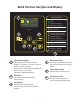
Mark IIXG User Interface and Display 1 SYSTEM STATUS 132 psi Ready 1 2 0.8A 0.7A 11.7 11.
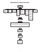
Mark IIXG User Menu Structure Main Menu Settings System Setup Date & Time Display Language/Units Passwords Time Date Daylight Saving Engine & Cranking Alarm Limits Feat. Settings Opt. Settings Timers Pressure On Delay Time Min.
Programming Notes The Firetrol Mark IIXG is multi-level password protected. User programmable functions are protected by a Level 1 password. LEVEL 1 PASSWORD 2-1-1-2 1 Indicates the level of password required to modify a setting. Note: Many menu settings feature an “enable/disable” option. These options are indicated by a “9” for enabled or a “x” for disabled. In many cases this can also be interpreted as “9” for yes or a “x” for no.
Mark IIXG User Menu Settings Note: Many menu settings feature an “enable/disable” option. These options are indicated by a "9” for enabled or a “x” for disabled. Indicates the level of password required to modify setting. 1 System Setup - Display SETTINGS Use and and DISPLAY SYSTEM SETUP 1 to confirm. CONTRAST arrows to set desired display contrast. Press SETTINGS Use BRIGHTNESS arrows to set desired display brightness.
SETTINGS DATE & TIME DAYLIGHT SAVING 1 arrows to enable or disable automatic Daylight Saving time adjustments. Press Use to confirm. Use arrows to set number of minutes to adjust for at the beginning or end of Daylight Saving time. Press to confirm. (+/-) (DST +) “Begin” - Hour Use arrows to set the hour of day that Daylight Saving time begins. Press to confirm. (DST +) “Begin” - Day Use Press arrows to set the day of the month that Daylight Saving time begins. to confirm.
PRESSURE SETTINGS OVERPRESSURE ALARM 1 arrows to enable or disable the overpressure alarm feature. Press Use Use Limit SETTINGS Use to confirm. arrows to set the pressure limit for the overpressure alarm. Press PRESSURE RECORDING - DELTA arrows to set pressure delta recording limit. Press to confirm. 1 to confirm. Note: Pressure will be recorded whenever pressure changes by more than set limit. Use arrows to enable or disable hourly pressure recording.
Use MAX ALARM LIMITS SETTINGS 1 arrows to set maximum voltage point for Battery Trouble alarm. Press to confirm. Use V MIN ALARM LIMITS SETTINGS 1 arrows to set minimum voltage point for AC Voltage Low alarm. Press to confirm. Use Use Use ENABLED 1 arrows to enable or disable the AC Voltage Low alarm. Press to confirm. V MAX ALARM LIMITS SETTINGS 1 arrows to set maximum voltage point for AC Voltage High alarm. Press ENABLED 1 arrows to enable or disable the AC Voltage High alarm.
FEATURE SETTINGS SETTINGS Use Press MANUAL TEST DURATION 1 arrows to set the minimum run time (duration) when manual test push-button is used (10 - 99 min.). to confirm. SETTINGS FEATURE SETTINGS PUMP RUN ALARM AUDIBLE 1 arrows to enable or disable the audible alarm for Pump Run. Press Use Use Press to confirm. COMMON ALARM 1 arrows to enable or disable the common alarm output (ALR relay) for Pump Run. to confirm.
AT 1 arrows to choose the time of day that the Weekly Test is performed. Press Use to confirm. FOR 1 arrows to choose the duration (engine run time) of the Weekly Test. Press Use to confirm. NOW IN WEEK 1 Use arrows to choose current time frame in reference to the Weekly Test schedule. Press to confirm.
SETTINGS Use Use Press FEATURE SETTINGS HIGH RESERVOIR AUDIBLE 1 arrows to enable or disable the audible alarm for High Reservoir Level. Press to confirm. COMMON ALARM 1 arrows to enable or disable the common alarm output (ALR relay) for High Reservoir Level. to confirm. PUMP ROOM 1 Use arrows to select the alarm output relay for High Reservoir Level (Disabled, PTR (Pump Room Trouble), ETR (Engine Trouble), Both PTR and ETR). Press to confirm.
REMOVE DRIVE 1 Use arrows to enable or disable the Remove Drive feature. Press to confirm. Much like a computer, the Remove Drive feature ensures file closure prior to removing the USB flash drive from the Mark IIXG. Use of this feature helps prevent file corruption. NOTE: The Mark IIXG also features an automatic daily save function. Every day at midnight (0:00) the events for that day are written to a file on the USB flash drive. This file is also a text file (.
FACTORY DIAGNOSTICS RAW INPUT: ANALOG Input values are shown. This information is for factory level troubleshooting purposes. RAW INPUT: DISCRETE Input values are shown. This information is for factory level troubleshooting purposes. RAW INPUT: KEYS Input values are shown. This information is for factory level troubleshooting purposes. RAW OUTPUT: DISCRETE Output values are shown. This information is for factory level troubleshooting purposes.
BATTERY CHARGER When installing the battery charger as a replacement part, it is necessary to verify the proper charger settings and adjust as necessary. 1. Incoming AC voltage 115 or 230 volts. 2. Battery voltage - 12 or 24 volts DC. 3. Battery type - Lead Acid / Ni-Cad 9 or 18 Cell / Ni-Cad 10 or 20 Cell. If battery charger is powered with the incorrect settings, damage to the charger and/or batteries may occur. The Firetrol® battery charger features a fully automatic 4 step charging cycle.