Foreword Your INFINITI represents a new way of thinking about vehicle design. It integrates advanced engineering and superior craftsmanship with a simple, refined aesthetic sensitivity associated with traditional Japanese culture. The result is a different notion of luxury and beauty.
WHEN READING THE MANUAL CALIFORNIA PROPOSITION 65 WARNING This manual includes information for all options available on this model. Therefore, you may find some information that does not apply to your vehicle. WARNING All information, specifications and illustrations in this manual are those in effect at the time of printing. INFINITI reserves the right to change specifications or design at any time without notice. IMPORTANT INFORMATION ABOUT THIS MANUAL You will see various symbols in this manual.
Table of Contents Illustrated table of contents 0 Safety — Seats, seat belts and supplemental restraint system 1 Instruments and controls 2 Pre-driving checks and adjustments 3 Display screen, heater, air conditioner and audio systems 4 Starting and driving 5 In case of emergency 6 Appearance and care 7 Maintenance and do-it-yourself 8 Technical and consumer information 9 Index 10 Z 05.11.1/S50-D/V5.
Z 05.11.1/S50-D/V5.
0 Illustrated table of contents Exterior ............................................................ 0-2 Instrument panel .............................................. 0-3 Meters and gauges ........................................... 0-4 Engine compartment ......................................... 0-5 VQ35DE engine ........................................... 0-5 VK45DE engine ........................................... 0-6 Z 05.11.1/S50-D/V5.
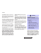
EXTERIOR 1. Hood (Page 3-24) 2. Headlight (P.2-21) and turn signal switch 3. Wiper and washer switch (P.2-21) 4. Windshield (P.8-21) 5. Sunroof (if so equipped) (P.2-43) 6. Power windows (P.2-41) 7. Recovery hook (P.6-16) 8. Fog light and switch (P.2-28) 9. Tires — Wheel and tires (P.8-35, 9-10) — Flat tire (P.6-2) 10. Mirrors (P.3-30) 11. Doors (P.3-3) — Keys — Door locks — Remote keyless entry system — Intelligent Key (if so equipped) 12. Lift gate (P.3-24) 13. Rear window wiper (P.8-23) 14.
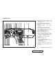
INSTRUMENT PANEL 1. Outside mirror remote control (P.3-31) 2. Headlight, fog light and turn signal switch (P.2-23) 3. Trip odometer reset knob (P.2-4) 4. Instrument brightness control switch (P.2-25) 5. Headlight aiming control switch (P.2-26) 6. Trip odometer select knob (P.2-4) 7. Steering switch for Audio (P.4-40)/ Bluetooth Hands-Free Phone System (if so equipped) (P.4-41) 8. Security indicator light (P.2-18) 9. Meters and gauges (P.2-3) 10. Driver supplemental air bag (P.1-37) 11.
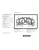
METERS AND GAUGES 19. Lane departure warning (LDW) switch (if so equipped) (P.2-30) 20. Hood release handle (P.3-24) 21. Fuse box (P.8-24) 22. SNOW mode switch (P.2-31) 23. Parking brake (P.5-18) 24. Vehicle dynamic control (VDC) OFF switch (P.2-31) 25. Tilting/telescopic steering wheel switch (P.3-28) 26. Storage box and power outlet (P.2-33, P.2-35) 27. Hazard warning flasher switch (P.2-28) 28. Automatic transmission selector lever (P.5-14) 29. Heated seat switch (P.2-29) 30. Clock (P.2-32) 31.
ENGINE COMPARTMENT VQ35DE ENGINE 1. Fuse/fusible link holder (P.8-24) 2. Battery (P.8-17) 3. Engine oil filler cap (P.8-11) 4. Brake fluid reservoir (P.8-16) 5. Engine coolant reservoir (P.8-9) 6. Window washer fluid reservoir (P.8-16) 7. Power steering fluid reservoir (P.8-15) 8. Radiator filler cap (P.8-9) 9. Drive belts (P.8-19) 10. Engine oil dipstick (P.8-11) 11. Air cleaner (P.8-20) SDI1991 Illustrated table of contents 0-5 Z 05.11.1/S50-D/V5.
VK45DE ENGINE 1. Fuse/fusible link holder (P.8-24) 2. Battery (P.8-17) 3. Engine oil filler cap (P.8-11) 4. Brake fluid reservoir (P.8-16) 5. Engine coolant reservoir (P.8-9) 6. Window washer fluid reservoir (P.8-16) 7. Power steering fluid reservoir (P.8-15) 8. Radiator filler cap (P.8-9) 9. Drive belts (P.8-19) 10. Engine oil dipstick (P.8-11) 11. Air cleaner (P.8-20) SDI1987 0-6 Illustrated table of contents Z 05.11.1/S50-D/V5.
1 Safety — Seats, seat belts and supplemental restraint system Seats................................................................ 1-2 Front power seat adjustment........................ 1-2 Rear seat adjustment................................... 1-4 Head restraint adjustment ........................... 1-6 Active head restraint (front seats)................. 1-7 Armrest ....................................................... 1-7 Seat belts .........................................................
SEATS FRONT POWER SEAT ADJUSTMENT WARNING SSS0133B WARNING O Do not ride in a moving vehicle when the seatback is reclined. This can be dangerous. The shoulder belt will not be against your body. In an accident, you could be thrown into it and receive neck or other serious injuries. You could also slide under the lap belt and receive serious internal injuries. O For the most effective protection when the vehicle is in motion, the seat should be upright.
SSS0474 SSS0475 Forward and backward Reclining Seat lifter 1 forward or backward Moving the switch j will slide the seat forward or backward to the desired position. 2 backward until Move the recline switch j the desired angle is obtained. To bring the seatback forward again, move the switch 2 forward. j Push the front or rear end of the switch up or down to adjust the height and angle of the seat.
B and fold the seatthe luggage room j back. 5. When resetting the seat, be sure to install the head restraints. WARNING SSS0476 Lumbar support (if so equipped for driver’s seat) The lumbar support feature provides lower back support to the driver. Push the front 1 or back j 2 end of the switch to adjust j the seat lumbar area. O Never allow anyone to ride in the cargo area or on the rear seat when it is in the fold-down position.
luggage is on the rear seat or any cup is in the cup holder. O Head restraints should be adjusted properly as they may provide significant protection against injury in an accident. Always replace and adjust them properly if they have been removed for any reason. O If the head restraints are removed for any reason, they should be securely stored to prevent them from causing injury to passengers or damage to the vehicle in case of sudden braking or an accident.
you could be thrown into it and receive neck or other serious injuries. You could also slide under the lap belt and receive serious internal injuries. O For the most effective protection when the vehicle is in motion, the seat should be upright. Always sit well back in the seat and adjust the seat belt properly. See “Precautions on seat belt usage” later in this section. O After adjustment, gently rock in the seat to make sure it is securely locked.
SSS0508 ACTIVE HEAD RESTRAINT (front seats) WARNING O Always adjust the head restraints properly as specified in the previous section. Failure to do so can reduce the effectiveness of the active head restraint. O Active head restraints are designed to supplement other safety systems. Always wear seat belts. No system canprevent all injuries in any accident. O Do not attach anything to the head restraint stalks. Doing so could impair active head restraint function.
SEAT BELTS PRECAUTIONS ON SEAT BELT USAGE If you are wearing your seat belt properly adjusted, and you are sitting upright and well back in your seat, your chances of being injured or killed in an accident and/or the severity of injury may be greatly reduced. INFINITI strongly encourages you and all of your passengers to buckle up every time you drive, even if your seating position includes a supplemental air bag.
SSS0136A WARNING O O Every person who drives or rides in this vehicle should use a seat belt at all times. Children should be properly restrained in the rear seat and, if appropriate, in a child restraint. The seat belt should be properly adjusted to a snug fit. Failure to do so may reduce the effectiveness of the entire restraint system and increase the chance or severity of injury in an accident. Serious injury or death can occur if the seat belt is not worn properly.
SSS0134A O Removal and installation of the pretensioner seat belt system components should be done by an INFINITI dealer. O All seat belt assemblies, including retractors and attaching hardware, should be inspected after any collision by an INFINITI dealer. INFINITI recommends that all seat belt assemblies in use during a collision be replaced unless the collision was minor and the belts show no damage and continue to operate properly.
CHILD SAFETY Children need adults to help protect them. They need to be properly restrained. In addition to the general information in this manual, child safety information is available from many other sources, including doctors, teachers, government traffic safety offices, and community organizations. Every child is different, so be sure to learn the best way to transport your child.
Larger children Children who are too large for child restraints should be seated and restrained by the seat belts which are provided. The seat belt may not fit properly if the child is less than 4 feet 9 inches (142.5 cm) tall and weighs between 40 lb (18 kg) and 80 lb (36 kg). A booster seat should be used to obtain proper seat belt fit.
Rear seat SSS0293 you could be thrown into it and receive neck or other serious injuries. You could also slide under the lap belt and receive serious internal injuries. O For the most effective protection when the vehicle is in motion, the seat should be upright. Always sit well back in the seat and adjust the seat belt properly. Front seat SSS0290 Fastening the seat belts 1. Adjust the seat. See “Seats” earlier in this section. 2.
straint installation. It is referred to as the automatic locking mode. To increase your confidence in the seat belts, check the operation as follows: When the locking mechanism is activated the seat belt cannot be extended again until the seat belt tongue is detached from the buckle and fully retracted. For additional information, see “Child restraints” later in this section. O grasp the shoulder belt and pull quickly forward. The retractor should lock and restrict further belt movement.
WARNING SSS0351 Shoulder belt height adjustment (for front seats) The shoulder belt anchor height should be adjusted to the position best suited for you. (See “Precautions on seat belt usage” earlier in this section.) To adjust, pull the A , and then move the release button j shoulder belt anchor to the desired position, so that the belt passes over the center of the shoulder. The belt should be away from your face and neck, but not falling off of your shoulder.
Stowing rear center seat belt When folding down the rear seat, the rear center seat belt can be retracted into a stowed position as follows: 1 so that 1. Hold the connector tongue j the seat belt does not retract suddenly when the tongue is released from the connector buckle. A 2. Insert a suitable tool such as a key j into the connector buckle and release the connector tongue. 2 . 3. Fold the connector as illustrated j SSS0241 4. Then secure the connector tongue into 3 in the ceiling.
O Attaching rear center seat belt If the rear center seat belt connector and the seatbacks are not secured in the correct position, serious personal injury may result in an accident or sudden stop. Always be sure the rear center seat belt connector tongue and connector buckle are attached. Disconnect only when folding down the rear seat. To connect the buckle: 1. Pull out the seat belt tongue from the 1 in the ceiling. retractor base j 2. Pull the seat belt and secure the con2 .
O O When attaching the rear center seat belt connector, be certain that the seatbacks are completely secured in the latched position and the rear center seat belt connector is completely secured. If the rear center seat belt connector and the seatbacks are not secured in the correct position, serious personal injury may result in an accident or sudden stop. WARNING O O Adults and children who can use the standard seat belt should not use an extender.
CHILD RESTRAINTS SSS0099 SSS0269 PRECAUTIONS ON CHILD RESTRAINTS for even the strongest adult to resist the forces of a severe accident. The child could be crushed between the adult and parts of the vehicle. Also, do not put the same seat belt around both your child and yourself. WARNING O O Infants and small children should always be placed in an appropriate child restraint while riding in the vehicle. Failure to use a child restraint can result in serious injury or death.
Canadian Motor Vehicle Safety Standard 213. O O check the child restraint in your vehicle to be sure it is compatible with the vehicle’s seat and seat belt system. O if the child restraint is compatible with your vehicle, place your child in the child restraint and check the various adjustments to be sure the child restraint is compatible with your child. Choose a child restraint that is designed for your child’s height and weight. Always follow all recommended procedures. All U.S.
CHILD RESTRAINT INSTALLATION ON REAR SEAT OUTBOARD OR CENTER POSITIONS WARNING O The three-point seat belt in your vehicle is equipped with an automatic locking mode retractor which must be used when installing a child restraint. O Failure to use the automatic locking mode will result in the child restraint not being properly secured. The restraint could tip over or otherwise be unsecured and cause injury to the child in a sudden stop or collision.
SSS0253E 2. Route the seat belt tongue through the child restraint and insert it into the buckle until you hear and feel the latch engage. Be sure to follow the child restraint manufacturer’s instructions for belt routing. SSS0254E 3. Pull on the shoulder belt until all of the belt is fully extended. At this time, the belt retractor is in the automatic locking mode (child restraint mode). It reverts back to emergency locking mode when the belt is fully retracted. SSS0332A 4.
6. Check that the retractor is in the automatic locking mode by trying to pull more belt out of the retractor. If you cannot pull any more belt webbing out of the retractor, the belt is in the automatic locking mode. 7. Check to make sure that the child restraint is properly secured prior to each use. If the belt is not locked, repeat steps 3 through 6. SSS0333 5.
Rear center seat SSS0358 SSS0335 2. Route the seat belt tongue through the child restraint and insert it into the buckle until you hear and feel the latch engage. Be sure to follow the child restraint manufacturer’s instructions for belt routing. SSS0258A 3. Pull on the shoulder belt until all of the belt is fully extended. At this time, the belt retractor is in the automatic locking mode (child restraint mode). It reverts back to emergency locking mode when the belt is fully retracted.
6. Check that the retractor is in the automatic locking mode by trying to pull more belt out of the retractor. If you cannot pull any more belt webbing out of the retractor, the belt is in the automatic locking mode. 7. Check to make sure that the child restraint is properly secured prior to each use. If the belt is not locked, repeat steps 3 through 6. SSS0259A 4. Allow the seat belt to retract. Pull up the shoulder belt to remove any slack in the belt.
back. A label is attached to the seatback to help you locate the LATCH system anchors. WARNING O Attach LATCH system compatible child restraints only at the locations shown. If a child restraint is not secured properly, your child could be seriously injured or killed in an accident. O Do not secure a child restraint in the rear center seating position using the LATCH system anchors. The child restraint will not be secured properly.
WARNING Inspect the lower anchors by inserting your fingers into the lower anchor area and feeling to make sure there are no obstructions over the LATCH system anchors, such as seat belt webbing or seat cushion material. The child restraint will not be secured properly if the LATCH system anchors are obstructed. 1. To install the LATCH system compatible child restraint, insert the child restraint LATCH system anchor attachments into the anchor points on the seat.
O After removing a rear seat head restraint for top tether installation, store it securely to prevent it from causing injury to passengers or damage to the vehicle in case of sudden braking or an accident. Always replace it and adjust properly when top tether is no longer in use. If your child restraint has a top tether strap, it must be secured to the anchor point provided behind its position.
SSS0300A CHILD RESTRAINT INSTALLATION ON FRONT PASSENGER SEAT WARNING O Never install a rear-facing child restraint in the front passenger seat. Supplemental front air bags inflate with great force. A rear-facing child restraint could be struck by the supplemental front air bag in a crash and could seriously injure or kill your child. O INFINITI recommends that child restraints be installed in the rear seat.
The back of the child restraint should be secured against the vehicle seatback. If necessary, adjust or remove the head restraint to obtain the correct child restraint fit. See “Head restraint adjustment” earlier in this section. If the head restraint is removed, store it in a secure place. Be sure to install the head restraint when the child restraint is removed.
SSS0361 3. Pull on the shoulder belt until all of the belt is fully extended. At this time, the belt retractor is in the automatic locking mode (child restraint mode). It reverts back to emergency locking mode when the belt is fully retracted. SSS0331A 4. Allow the seat belt to retract. Pull up on the shoulder belt to remove any slack in the belt. SSS0302C 5.
BOOSTER SEATS able to properly secure the restraint, move the restraint to another rear seating position and try again, or try a different child restraint. Not all child restraints fit in all types of vehicles. 6. Check that the retractor is in the automatic locking mode by trying to pull more belt out of the retractor. If you cannot pull any more belt webbing out of the retractor, the belt is in the automatic locking mode. 7.
LRS0455 WARNING Do not use towels, books, pillows or other items in place of a booster seat. Items such as these may move during normal driving or a collision and result in serious injury or death. Booster seats are designed to be used with a lap/shoulder belt. Booster seats are designed to properly route the lap and shoulder portions of the seat belt over the strongest portions of a child’s body to pro- LRS0453 vide the maximum protection during a collision.
O If the booster seat is compatible with your vehicle, place your child in the booster seat and check the various adjustments to be sure the booster seat is compatible with your child. Always follow all recommended procedures. All U.S. states and Canadian provinces or territories require that infants and small children be restrained in an approved child restraint at all times while the vehicle is being operated.
is interfering with the proper booster seat fit, try another seating position or a different booster seat. 3. Position the lap portion of the seat belt low and snug on the child’s hips. Be sure to follow the booster seat manufacturer’s instructions for adjusting the belt routing. Outboard position LRS0452 BOOSTER SEAT INSTALLATION ON REAR SEAT OUTBOARD OR CENTER POSITIONS CAUTION Do not use the lap/shoulder belt automatic locking mode when using a booster seat with the seat belts.
“Front passenger air bag and status light” later in this section for details. If you must install a booster seat in the front seat, follow these steps: 1. Move the seat to the rearmost position. 2. Position the booster seat on the seat. Only place it in a front facing direction. Always follow the booster seat manufacturer’s instructions. LRS0454 BOOSTER SEAT INSTALLATION ON FRONT PASSENGER SEAT WARNING INFINITI recommends that child restraints be installed in the rear seat.
SUPPLEMENTAL RESTRAINT SYSTEM PRECAUTIONS ON SUPPLEMENTAL RESTRAINT SYSTEM This Supplemental Restraint System (SRS) section contains important information concerning the driver and passenger front impact supplemental air bags (INFINITI advanced air bag system), front seat sideimpact supplemental air bags, curtain side-impact and rollover air bags and front seat pre-tensioner seat belts.
are at greater risk of injury or death in a crash. You may also receive serious or fatal injuries from the supplemental front air bag if you are up against it when it inflates. Always sit back against the seatback and as far away as practical from the steering wheel or instrument panel. Always use the seat belts. O The driver and front passenger seat belt buckles are equipped with sensors that detect if the seat belts are fastened.
O Keep hands on the outside of the steering wheel. Placing them inside the steering wheel rim could increase the risk that they are injured when the supplemental front air bag inflates. SSS0132B Safety — Seats, seat belts and supplemental restraint system 1-39 Z 05.11.1/S50-D/V5.
SSS0006 SSS0008 SSS0099 SSS0007 SSS0009 SSS0100 1-40 Safety — Seats, seat belts and supplemental restraint system Z 05.11.1/S50-D/V5.
WARNING O Never let children ride unrestrained or extend their hands or face out of the window. Do not attempt to hold them in your lap or arms. Some examples of dangerous riding positions are shown in the previous illustrations. O Children may be severely injured or killed when the supplemental front air bags, side air bags or curtain sideimpact and rollover air bags inflate if they are not properly restrained. Preteens and children should be properly restrained in the rear seat, if possible.
SSS0140 window or lean against the door. Some examples of dangerous riding positions are shown in the illustrations. O SSS0159 O Do not use seat covers on the front seatbacks. They may interfere with supple mental side air bag inflation. When sitting in the rear seat, do not hold onto the seatback of the front seat. If the side air bag inflates, you may be seriously injured. Be especially careful with children, who should always be properly restrained.
The driver supplemental front air bag is located in the center of the steering wheel. The front passenger supplemental front air bag is mounted in the instrument panel above the glove box. The supplemental front air bags are designed to inflate in higher severity frontal collisions, although they may inflate if the forces in another type of collision are similar to those of a higher severity frontal impact. They may not inflate in certain frontal collisions.
the front passenger air bag may be automatically turned OFF under some conditions, depending on the weight detected on the passenger seat and how the seat belt is used. If the front passenger air bag is OFF, the passenger air bag status light will be illuminated (if the seat is unoccupied, the light will not be illuminated, but the air bag will be off.). See “Front passenger air bag and status light” later in this section for further details.
all instructions in this manual concerning the use of seats, seat belts and child restraints can increase the risk or severity of injury in an accident. Status light: The front passenger air bag status light is located on the map light cover. The light operates as follows: SSS0614 Front passenger air bag and status light WARNING The front passenger air bag is designed to automatically turn OFF under some conditions. Read this section carefully to learn how it operates.
tected and cause the air bag to turn OFF. The occupant classification sensor operation can vary depending on the front passenger seat belt sensors. The front passenger seat belt sensors are designed to detect if the seat belt is buckled and the amount of tension on the seat belt, such as when it is in the automatic locking mode (child restraint mode).
will not illuminate even though the air bag is OFF. Other supplemental front air bag precautions If such situations happen, properly position and restrain the occupant or child restraint. Otherwise reposition the occupant or child restraint in a rear seat. If you have any questions about whether your passenger air bag is working as designed, your INFINITI dealer can confirm that it is working properly by using a special tool.
O No unauthorized changes should be made to any components or wiring of the seat belt system. This may affect the supplemental front air bag system. Tampering with the seat belt system may result in serious personal injury. O Work on and around the supplemental front air bag system should be done by an INFINITI dealer. Installation of electrical equipment should also be done by an INFINITI dealer. The Supplemental Restraint System (SRS) wiring should not be modified or disconnected.
impact and rollover air bags are designed to inflate in higher severity side collisions, although they may inflate if the forces in another type of collision are similar to those of a higher severity side impact. They are designed to inflate on the side where the vehicle is impacted. They may not inflate in certain side collisions. Curtain side-impact and rollover air bags are also designed to inflate in certain types of rollover collisions or near rollovers.
O O O O No unauthorized changes should bemade to any components or wiring of this side air bag and curtain side-impact air bag system. This is to prevent accidental inflation of the side air bag and curtain side-impact air bag or damage to the side air bag and curtain side-impact air bag system. Do not make unauthorized changes to your vehicle’s electrical system, suspension system or side panel. This could affect proper operation of the supplemental side air bag and curtain sideimpact air bag system.
The front seat pre-tensioner seat belt system activates in conjunction with the front supplemental air bag systems. Working with the seat belt retractor, it helps tighten the seat belt when the vehicle becomes involved in certain types of collisions, helping to restrain front seat occupants. When selling your vehicle, we request that you inform the buyer about the pretensioner seat belt system and guide the buyer to the appropriate sections in this Owner’s Manual.
air bag modules, pre-tensioner seat belts and all related wiring. After turning the ignition switch to the ON or START position, the supplemental air bag warning light illuminates. The supplemental air bag warning light will turn off after about 7 seconds if the system is operational.
pointed out to the person conducting the maintenance. The ignition switch should always be in the LOCK position when working under the hood or inside the vehicle. WARNING O Once a supplemental front air bag, supplemental side air bag or curtain air bag has inflated, the air bag module will not function again and must be replaced. Additionally, if any of the supplemental front air bags inflate, the activated pretensioner seat belts must also be replaced.
2 Instruments and controls Instrument panel .............................................. 2-2 Meters and gauges ........................................... 2-3 Speedometer and odometer......................... 2-4 Tachometer ................................................. 2-4 Engine coolant temperature gauge ............... 2-5 Fuel gauge .................................................. 2-5 Compass display ..............................................
Tonneau cover (if so equipped) .................. Windows ........................................................ Power windows ......................................... Sunroof (if so equipped).................................. Automatic sunroof ..................................... Interior light ................................................... Room light................................................. Map light .................................................. Ceiling light (if so equipped) .......
INSTRUMENT PANEL SSI0182 1. Outside mirror remote control 2. Headlight, fog light and turn signal switch 3. Trip odometer reset knob 4. Instrument brightness control switch 5. Headlight aiming control switch 6. Trip odometer select knob 7. Steering switch for Audio/Bluetooth Hands-Free Phone System (if so equipped) 8. Security indicator light 9. Meters and gauges 10. Driver supplemental air bag 11. Cruise control main/set switch or Intelligent cruise control switch (if so equipped) 12.
METERS AND GAUGES 24. Vehicle dynamic control (VDC) OFF switch 25. Tilting/telescopic steering wheel switch 26. Storage box and power outlet 27. Hazard warning flasher switch 28. Automatic transmission selector lever 29. Heated seat switch 30. Clock 31. Automatic climate control system 32. Glove box *: Refer to the separate Navigation System Owner’s Manual. (if so equipped) SIC2135 1. Warning/Indicator lights play (if so equipped) 2. Tachometer 3. Speedometer 6.
Odometer/Twin trip odometer The odometer/twin trip odometer are displayed when the ignition switch is in the ON position. 1 records the total distance The odometer j the vehicle has been driven. 2 records the disThe twin trip odometer j tance of individual trips. Changing the display: 3 changes the disPushing the trip knob j play as follows: SIC2551 TRIP A → TRIP B → TRIP A Resetting the trip odometer: TACHOMETER 4 to reset Push and hold the reset knob j the trip odometer to zero.
CAUTION SIC2137A ENGINE COOLANT TEMPERATURE GAUGE The gauge indicates the engine coolant temperature. The engine coolant temperature is normal when the gauge indicates within the range A . j The engine coolant temperature will vary with the outside air temperature and driving conditions. If the gauge indicates engine coolant temperature near the hot (H) end of the normal range, reduce vehicle speed to decrease temperature.
COMPASS DISPLAY A comes on The low fuel warning light j when the fuel tank is getting low. Refuel as soon as it is convenient, preferably before the gauge reaches E. There will be a small reserve of fuel in the tank when the fuel gauge needle reaches E. A is pushed, When the compass switch j B will indicate the dithe compass display j rection the vehicle is heading. The indicates that the fuel-filler door is located on the passenger’s side of the vehicle.
Zone variation change procedure The difference between magnetic north and geographical north is known as variance. In some areas, this difference can sometimes be great enough to cause false compass readings. Follow these instructions to set the variance for your particular location if this happens: 1. Push the compass switch for more than 3 seconds. The current zone number will appear in the display. 2. Find your current location and variance number on the zone map. 3.
3. The display returns to the normal compass mode within 10 seconds after the switch is released. 4. If the vehicle changes zone, repeat steps 1 thru 3. See map. cleaner directly on the mirror as it may cause the liquid cleaner to enter the mirror housing. O If the compass deviates from the correct direction after repeated adjustment, have the compass checked at an INFINITI dealer. O The compass may not indicate the correct compass point in tunnels or while driving up or down a steep hill.
WARNING/INDICATOR LIGHTS AND AUDIBLE REMINDERS All-Wheel Drive (AWD) warning light (AWD models) or or Anti-lock brake warning light Intelligent Key warning light (if so equipped) Front passenger air bag status light Lane Departure Warning (LDW) system indicator light (Orange; if so equipped) High beam indicator light (Blue) Automatic transmission check warning light Low fuel warning light Preview Function warning light (Orange; if so equipped) Low tire pressure warning light Brake warning light
WARNING LIGHTS All-Wheel Drive (AWD) warning light (AWD models) The AWD warning light comes on when the ignition switch is turned to ON. It turns off soon after the engine is started. If the AWD system malfunctions or the revolution, or radius of the front and the rear wheel are different, the warning light will either remain illuminated or blink. See “All-Wheel Drive (AWD)” in the “5. Starting and driving” section.
Preview Function warning light (Orange: if so equipped) The light comes on if there is a malfunction in the Brake Assist (with Preview Function) system. or O Your brake system may not be working properly if the warning light is on. Driving could be dangerous. If you judge it to be safe, drive carefully to the nearest service station for repairs. Otherwise, have your vehicle towed because driving it could be dangerous.
Engine oil pressure warning light This light warns of low engine oil pressure. If the light flickers or comes on during normal driving, pull off the road in a safe area, stop the engine immediately and call an INFINITI dealer or other authorized repair shop. The engine oil pressure warning light is not designed to indicate a low oil level. Use the dipstick to check the oil level. See “Engine oil” in the “8. Maintenance and doit-yourself” section.
Low tire pressure warning light Your vehicle is equipped with a tire pressure monitoring system (TPMS) that monitors the tire pressure of all tires except the spare. The low tire pressure warning light warns of low tire pressure or indicates that the TPMS is not functioning properly. After the ignition switch is turned ON, this light illuminates for about 1 second and turns off.
WARNING O O O If the light does not illuminate with the ignition switch turned ON, have the vehicle checked by an INFINITI dealer as soon as possible. If the light illuminates while driving, avoid sudden steering maneuvers or abrupt braking, reduce vehicle speed, pull off the road to a safe location and stop the vehicle as soon as possible. Serious vehicle damage could occur and may lead to an accident and could result in serious personal injury. Check the tire pressure for all four tires.
chime will sound for about 6 seconds unless the driver’s seat belt is securely fastened. O The supplemental air bag warning light remains on after approximately 7 seconds. The seat belt warning light for the front passenger will illuminate if the seat belt is not fastened when the front passenger’s seat is occupied (if so equipped). For 5 seconds after the ignition switch is in the ON position, the system does not activate the warning light for the front passenger.
Front passenger air bag status light The front passenger air bag status light ( ) will be lit and the passenger front air bag will be OFF depending on how the front passenger seat is being used. For front passenger air bag status light operation, see “INFINITI advanced air bag system” in the “1. Safety — Seats, seat belts and supplemental restraint system” section of this manual.
b) Avoid hard acceleration or deceleration. c) Avoid steep uphill grades. d) If possible, reduce the amount of cargo being hauled or towed. The malfunction indicator lamp may stop blinking and come on steady. Have the vehicle inspected by an INFINITI dealer. You do not need to have your vehicle towed to the dealer.
SECURITY SYSTEMS Brake pad wear warning system is armed. It is not, however, a motion detection type system that activates when a vehicle is moved or when a vibration occurs. The disc brake pads have audible wear warnings. When a brake pad requires replacement, it will make a high pitched scraping sound when the vehicle is in motion whether or not the brake pedal is depressed. Have the brakes checked as soon as possible if the warning sound is heard.
When using the remote keyless entry, the hazard indicators will operate as shown in “Remote keyless entry system” or “Intelligent Key system” in the “3. Pre-driving checks and adjustments” section. SIC2153 How to arm the vehicle security system 1. Close all windows. The system can be armed even if the windows are open. 2. Remove the key from the ignition switch. 3. Close and lock all doors and the hood.
If the system does not operate as described above, have it checked by an INFINITI dealer. INFINITI VEHICLE IMMOBILIZER SYSTEM The INFINITI Vehicle Immobilizer System will not allow the engine to start without the use of the registered key. If the engine fails to start using the registered key (for example, when interference is caused by another registered key, an automated toll road device or automated payment device on the key ring), restart the engine using the following procedures: 1.
WINDSHIELD WIPER AND WASHER SWITCH If INFINITI Vehicle Immobilizer System is malfunctioning, this light will remain on while the ignition switch is in the ON position. ally. See “How to use the SETTING button” in the “4. Display screen, heater, air conditioner and audio systems” section. If the light still remains on and/or the engine will not start, see an INFINITI dealer for INFINITI Vehicle Immobilizer System service as soon as possible.
REAR WINDOW WIPER AND WASHER SWITCH CAUTION O Do not operate the washer continuously for more than 30 seconds. O Do not operate the washer if the reservoir tank is empty. O Do not fill the window washer reservoir tank with washer fluid concentrates at full strength. Some methyl alcohol based washer fluid concentrates may permanently stain the grille if spilled while filling the window washer reservoir tank.
REAR WINDOW AND OUTSIDE MIRROR DEFROSTER SWITCH XENON HEADLIGHTS washer fluid concentrates may permanently stain the grille if spilled while filling the window washer reservoir tank. O HEADLIGHT AND TURN SIGNAL SWITCH WARNING Pre-mix washer fluid concentrates with water to the manufacturer’s recommended levels before pouring the fluid into the window washer reservoir tank. Do not use the window washer reservoir tank to mix the washer fluid concentrate and water.
O The life of xenon headlights will be shortened by frequent on-off operation. It is generally desirable not to turn off the headlights for short intervals (for example, when the vehicle stops at a traffic signal). Even when the daytime running lights are active (Canada only), the xenon headlights do not turn on. This way the life of the xenon headlights is not reduced.
The autolight system can turn on the headlights automatically when it is dark, turn off the headlights when it is light, and keep the headlights on for up to 45 seconds after you turn the switch to OFF and open any door then close all the doors. If the ignition switch is turned OFF and one of the doors is opened and this condition is continued, the headlights remain ON for 5 minutes.
Battery saver system O When the headlight switch is in the or position while the ignition switch is in the ON position, the lights will automatically turn off 5 minutes after the ignition switch has been turned to the OFF position. SIC3122 Headlight beam select 1 j To select the low beam, put the lever in the neutral position as shown. 2 To select the high beam, push the lever j forward. Pull it back to select the low beam. 3 Pulling the lever toward you will flash j the headlight high beam.
When traveling with no heavy load or on a flat road, select position 0. WARNING Xenon headlights are extremely bright compared to conventional headlights. If the xenon headlights hit the rearview mirror of the vehicle ahead or the windshield of the oncoming vehicle, the driver of these vehicles may have difficulty driving because of the brightness. Use the headlight aiming control switch to lower the light axis. See “Xenon headlights” earlier in this section for additional information.
HAZARD WARNING FLASHER SWITCH SIC3123 SIC3057 TURN SIGNAL SWITCH FOG LIGHT SWITCH 1 Turn signal j To turn the fog lights on, turn the headlight switch to the position, then turn the switch to the position. To turn them off, turn the switch to the OFF position. Move the lever up or down to signal the turning direction. When the turn is completed, the turn signals cancel automatically. 2 Lane change signal j To indicate a lane change, move the lever up or down to the point where lights begin flashing.
HORN O Do not use the hazard warning flashers while moving on the highway unless unusual circumstances force you to drive so slowly that your vehicle might become a hazard to other traffic. O Turn signals do not work when the hazard warning flasher lights are on. HEATED SEATS (if so equipped) The flasher can be actuated with the ignition switch either off or on. SIC2143 To sound the horn, push around the horn marks of the steering wheel. WARNING Do not disassemble the horn.
LANE DEPARTURE WARNING (LDW) SWITCH (if so equipped) C will The indicator light in the switch j illuminate when low or high is selected. O The heater is controlled by a thermostat, automatically turning the heater on and off. The indicator light will remain on as long as the switch is on. Do not place anything hard or heavy on the seat or pierce it with a pin or similar object. This may result in damage to the heater.
SNOW MODE SWITCH VEHICLE DYNAMIC CONTROL (VDC) OFF SWITCH Push the LDW switch again or restart the engine to turn the system on. Modes can be changed to automatic mode or manual mode by pushing and holding the LDW switch for more than 4 seconds while the LDW system ON indicator is off. See “Lane departure warning (LDW) system” in the “5. Starting and driving” section.
CLOCK POWER OUTLET Push the VDC OFF switch again or restart the engine to turn ON the system. See “Vehicle dynamic control (VDC) system” in the “5. Starting and driving” section. CAUTION SIC2772 If the power supply is disconnected, the clock will not indicate the correct time. Readjust the time. O The outlet and plug may be hot during or immediately after use. O This power outlet is not designed for use with a cigarette lighter unit.
overheat or the internal temperature fuse may open. O When not in use, be sure to close the cap. Do not allow water to contact the outlet. The power outlet is for powering electrical accessories such as cellular telephones. Console SIC2144 Front SIC3073 Instruments and controls 2-33 Z 05.11.1/S50-D/V5.
STORAGE CAUTION Rear SIC3124 O Do not use for anything other than sunglasses. O Do not leave sunglasses in the sunglasses holder while parking in direct sunlight. The heat may damage the sunglasses. SIC1844A SUNGLASSES HOLDER The sunglasses holder can be opened by A . pushing the button j WARNING Luggage room O The sunglasses holder should not be used while driving so full attention may be given to vehicle operation. O Keep the sunglasses holder closed while driving to prevent an accident.
STORAGE BOX CAUTION WARNING O Avoid abrupt starting and braking when the cup holder is being used to prevent spilling the drink. If the liquid is hot, it can scald you or your passenger. O Use only soft cups in the cup holder. Hard objects can injure you in an accident. The storage box should not be used while driving so full attention may be given to vehicle operation. A as ilTo open, push the storage box lid j lustrated. Do not place valuable items in the storage box.
SIC3118 SIC2149 SIC1888A Front cup holder Rear cup holder GLOVE BOX 1 . To open the cup holder, push the lid j Push the cup holder opener switch to draw out the rear cup holder. 1 . To open the glove box, pull the handle j The flap will be folded down when inserting a large container. To close, lower the cup holder lid and push it down lightly. To clean the front cup holder, pull up the in2 and remove it. side tray j To close, push the lid in until the lock latches.
WARNING Keep glove box lid closed while driving tohelp prevent injury in an accident or a sudden stop. Instruments and controls 2-37 Z 05.11.1/S50-D/V5.
CONSOLE BOX WARNING The center console box should not be used while driving so full attention may be given to vehicle operation. CAUTION To avoid being pinched, do not place your fingers near the hinge when opening/ closing the console box. A is pushed, the upper When the button j case is available for storing some small B is pulled, the botitems. When the lever j tom case is available for storing some larger ones. SIC3074 2-38 Instruments and controls Z 05.11.1/S50-D/V5.
SIC3151 LUGGAGE FLOOR BOXES (if so equipped) To open the luggage floor boxes: 1. Raise the luggage box lid. 1 and insert it 2. Remove the assist bar j 2 . into the slot j SIC2154 CARD HOLDER (for driver’s side) A in To use the card holder, slide your card j B . after lowering the sun visor j SIC2151 CARGO NET (if so equipped) The cargo net helps keep packages in the cargo area from moving around while your vehicle is driven. To install the cargo net, attach the hooks to the retainers.
WARNING In a sudden stop or collision, unsecured cargo could cause personal injury. O Be sure to secure all four hooks into the retainers. The cargo restrained in the net must not exceed 30 lb (13.6 kg) or the net may not stay secured. O Never put anything on the tonneau cover, no matter how small. Any object on it could cause an injury in an accident or sudden stop. O Do not leave the tonneau cover in the vehicle with it disengaged from the holder.
WINDOWS POWER WINDOWS WARNING O Make sure that all passengers have their hands, etc. inside the vehicle while it is in motion and before closing the windows. Use the window lock switch to prevent unexpected use of the power windows. O Do not leave children unattended inside the vehicle. They could unknowingly activate switches or controls and become trapped in a window. Unattended children could become involved in serious accidents.
Locking passenger’s windows C is pushed in, only When the lock button j the driver side window can be opened or closed. Push it in again to cancel. Passenger side SIC2152A Main switch SIC2923 Passenger side power window switch Automatic operation (For front door windows) The passenger side switch will open or close only the corresponding window. To open or close the window, hold the switch A or up j B .
SUNROOF (if so equipped) The auto reverse function can be activated when a window is closed by automatic operation when the ignition switch is in the ON position or for about 45 seconds after the ignition switch is turned to the ACC, OFF or LOCK position. need not be held. The roof will automatically open or close all the way. To stop the roof, press the switch once more while it is opening or closing. To open or close the sunroof and stop on 1 the way, press the switch to the CLOSE j 2 side.
seconds after the ignition key is turned to the OFF position. Depending on the environment or driving conditions, the auto reverse function may be activated if an impact or load similar to something being caught in the sunroof occurs. WARNING O In an accident you could be thrown from the vehicle through an open sunroof. Always use seat belts and child restraints.
INTERIOR LIGHT O The driver’s door is opened and then closed while the key is removed from the ignition switch. O The key is removed from the ignition switch while all doors are closed. The light will turn off while the 30 second timer is activated, when: O The driver’s door is locked either with the keyfob, a key, the power door lock switch or using the Intelligent Key system. SIC1857A ROOM LIGHT The room light has a two-position switch; 1 and OFF j 2 .
SIC2179 SIC1858A CEILING LIGHT (if so equipped) REAR PERSONAL LIGHT The ceiling light has a three-position switch. The rear personal light has a three-position switch. B , When the switch is in the door position j the light will illuminate when the door is opened. Same as the door position of the interior light. B , When the switch is in the door position j the light will illuminate when the door is opened.
VANITY MIRROR LIGHT HomeLink UNIVERSAL TRANSCEIVER (if so equipped) LUGGAGE ROOM LIGHT This luggage room light has a threeposition switch. The HomeLink Universal Transceiver provides a convenient way to consolidate the functions of up to three individual handheld transmitters into one built-in device. A , When the switch is in the door position j the light illuminates while the lift gate is opened. When the lift gate is closed, the light will go off.
WARNING O O Do not use the HomeLink Universal Transceiver with any garage door opener that lacks safety stop and reverse features as required by federal safety standards. (These standards became effective for opener models manufactured after April 1, 1982). A garage door opener which cannot detect an object in the path of a closing garage door and then automatically stop and reverse, does not meet current federal safety standards.
programmed HomeLink button - releasing when the device begins to activate. 5. If the indicator light on the HomeLink blinks rapidly for two seconds and then turns solid, HomeLink has picked up a “rolling code” garage door opener signal. You will need to proceed with the next steps to train the HomeLink to complete the programming which may require a ladder and another person for convenience. SIC3041 3.
tinue to press and hold the HomeLink button (note steps 2 through 4 under “Programming HomeLink ”) while you press and re-press (“cycle”) your hand-held transmitter every 2 seconds until the indicator light flashes rapidly (indicating successful programming). NOTE: If programming a garage door opener, etc., it is advised to unplug the device during the “cycling” process to prevent possible damage to the garage door opener components.
IF YOUR VEHICLE IS STOLEN If your vehicle is stolen, you should change the codes of any non-rolling code device that has been programmed into HomeLink . Consult the Owner’s Manual of each device or call the manufacturer or dealer of those devices for additional information. When your vehicle is recovered, you will need to reprogram the HomeLink Universal Transceiver with your new transmitter information. FCC Notice: This device complies with FCC rules part 15.
MEMO 2-52 Instruments and controls Z 05.11.1/S50-D/V5.
3 Pre-driving checks and adjustments Keys (except Intelligent Key) ............................. 3-2 INFINITI Vehicle Immobilizer System keys... 3-2 Doors ............................................................... 3-3 Locking with key (Driver’s door only) ............ 3-3 Opening and closing windows with the key... 3-4 Locking with inside lock knob ...................... 3-4 Locking with power door lock switch ............ 3-4 Child safety rear door lock ...........................
KEYS (except Intelligent Key) 3. Valet key (With built-in transponder chip; INFINITI mark-black) The valet key cannot be used for glove box lock. 4. Key number plate To protect belongings when you leave a key with someone, give them the valet key only. 5. Wallet key 6. key case (Card type) A key number plate is supplied with your keys. Record the key number and keep it in a safe place (such as your wallet), not in the vehicle.
DOORS Do not allow the immobilizer system key, which contains an electrical transponder, to come into contact with salt water. This could affect system function. WARNING O Always have the doors locked while driving. Along with the use of seat belts, this provides greater safety in the event of an accident by helping to prevent persons from being thrown from the vehicle. This also helps keep children and others from unintentionally opening the doors, and will help keep out intruders.
key can only be removed and inserted) and turning it to the rear again within 5 seconds will unlock all doors. (including the lift gate) and fuel-filler door. OPENING AND CLOSING WINDOWS WITH THE KEY The driver’s door key operation allows you to open and close the front windows simultaneously. To open the windows, turn the driver’s door key cylinder to the rear of the vehicle for longer than 1 second. The door is unlocked and the window keeps opening while turning the key.
REMOTE KEYLESS ENTRY SYSTEM (models without Intelligent Key system) To unlock, push the power door lock switch 2 . to the unlock position j Lockout protection When the power door lock switch (driver or front passenger) is moved to the lock position with the key in the ignition and any door open, all doors will lock and unlock automatically. This helps to prevent the keys from being accidentally locked inside the vehicle.
O Do not allow the keyfob to become wet. O Do not drop the keyfob. O Do not strike the keyfob sharply against another object. O Do not place the keyfob for an extended period in an area where temperatures exceed 140°F (60°C). If a keyfob is lost or stolen, INFINITI recommends erasing the ID code of that keyfob. This will prevent the keyfob from unauthorized use to unlock the vehicle. For information regarding the erasing procedure, please contact an INFINITI dealer.
screen, heater, air conditioner and audio systems”. Locking doors and fuel-filler door 1. Remove the ignition key.*1,*2 2. Close all the doors.*3 1 on the keyfob. 3. Push the LOCK button j 4. All the doors and fuel-filler door will lock. SPA1260 If hazard indicator and horn mode is not necessary, you can switch to hazard indicator only mode by following the switching procedure. In hazard indicator only mode, when the 1 is pushed, the hazard indiLOCK button j cator flashes twice.
*2: Doors lock with the keyfob while the ignition switch is in the ON position. However, the hazard indicator and horn will not function. *3: Doors lock with the keyfob while any door is open. However, the hazard indicator and horn will not function. Unlocking doors and fuel-filler door 2 on the key1. Push the UNLOCK button j fob once.
INTELLIGENT KEY SYSTEM (if so equipped) The Intelligent Key uses coded radio signals to communicate with the vehicle. When the Intelligent Key is near the vehicle, such as in your pocket or purse, it allows the vehicle to be locked, unlocked, or started without inserting the ignition key. It is also possible to use the remote control entry function. CAUTION O Be sure to carry the Intelligent Key with you. O Do not leave the vehicle with the Intelligent Key inside.
*: Refer to “INFINITI Vehicle Immobilizer System keys” earlier in this section. WARNING O The Intelligent Key transmits radio waves that can adversely affect medical electric equipment. O If you have a pacemaker, you should contact the medical equipment manufacturer to ask if it will be affected by the Intelligent Key signal. The valet key cannot be used for the glove box lock. To protect belongings when you leave a key with someone, give them the valet key only. SPA1873 1. 2. 3. 4.
— Do not use a magnet key holder. DOOR LOCKS/UNLOCKS PRECAUTION — Do not place the Intelligent Key near an electric appliance such as a television set or personal computer. O After locking with the door handle request switch, make sure the doors are securely locked. — Do not place the Intelligent Key in a storage area (for example, a door pocket or glove box). It could be damaged or activated unexpectedly.
3. Push any front door or the lift gate handle request switch while carrying the Intelligent Key with you.*4 4. All the doors, lift gate and fuel-filler door will lock. 5. The hazard indicator flashes twice and door buzzer sounds twice. The hazard indicator and horn mode also can be changed with vehicle electronic systems on the monitor. See “4. Display screen, heater, air conditioner and audio systems”.
However, when an Intelligent Key is inside the vehicle, doors can be locked with another Intelligent Key. O any door is opened O the ignition switch is pushed Unlocking doors O the mechanical key or the valet key is inserted into the ignition switch 1. Push the door handle request switch once. The interior light, ceiling light (if so equipped) and step light can be turned off without waiting for 30 seconds by turning the ignition switch to the ON position or by locking the doors.
D : ACC (Accessories) j This position activates electrical accessories such as the radio, when the engine is not running. E : ON (Normal operating position) j This position turns on the ignition system and electrical accessories. CAUTION Do not leave the vehicle with the ignition switch in ACC or ON positions when the engine is not running for an extended period.This can discharge the battery.
4. When the engine starts, release the ignition switch. O The engine may not start if the Intelligent Key is placed: WARNING Do not start the engine from outside the vehicle through the window. Doing so could lead to an accident and injury. Be sure to sit in the driver’s seat to use the key. SPA2193 Starting the engine When driving the vehicle, be sure to carry the Intelligent Key with you. 1. Securely depress the brake pedal. 2. Slowly push the ignition switch in.
The operating range of the door lock/unlock function is shown in the illustration. WARNING 1 59.1 in (1.5 m) from the outside mirrors j 2 59.1 in (1.5 m) from the rear door j When you leave the vehicle, be sure to observe the following: O corner pieces Shift the selector lever to P. (In other positions, the ignition switch will not return to LOCK.) O Securely return the ignition switch to LOCK. O Set the parking brake.
WARNING SIGNALS To help prevent the vehicle from moving unexpectedly by erroneous operation of the Intelligent Key or to help prevent the vehicle from being stolen, chime or beep sounds inside and outside the vehicle and a warning light comes on in the instrument panel. When a chime or beep sounds or the warning light comes on, be sure to check the vehicle and Intelligent Key. SPA1652 Operating range for engine start function The operating range for starting the engine is inside the vehicle.
If the chime sounds continuously when the driver’s door is opened, check the following: O The selector lever is in the P position and the ignition switch is turned to LOCK. O The mechanical key or the valet key is not inserted into the ignition switch. O The inside warning chime may stop when one of the following is performed. Warning for low battery power O This warning is to let you know that the battery of the Intelligent Key will run down soon. Replace it with a new one.
TROUBLE-SHOOTING GUIDE Symptom When pushing the door handle request switch The front door beep sounds for approximately 2 seconds When closing the doors The front door beep sounds for approximately 10 seconds The key warning light in the instrument panel blinks in red and the front door warning beep sounds for approximately 3 seconds. The front door beep sounds for approximately 3 seconds and all doors unlock.
Trouble-shooting examples When it is difficult to turn the ignition switch O Push the ignition switch again and turn it slowly. O While gently turning the steering wheel to the left or right, turn the ignition switch. OPERATION WITH INTELLIGENT REMOTE KEYLESS ENTRY SYSTEM It is possible to lock/unlock all doors, fuelfiller door, activate the panic alarm and open the windows by pushing the buttons on the Intelligent Key from outside the vehicle.
Locking doors and fuel-filler door: 1. Remove the mechanical key or the valet key if any key is in the ignition switch.*1 2. Close all the doors.*2 A on the Intelli3. Push the LOCK button j gent Key. 4. All the doors (including lift gate) and fuel-filler door will lock. SPA1260 indicator flashes twice and the horn chirps B once. When the UNLOCK button j is pushed, the hazard indicator flashes once.
Unlocking doors and fuel-filler door: O the ignition switch is pushed B on the In1. Push the UNLOCK button j telligent Key once. O the mechanical key or the valet key is inserted into the ignition switch O The driver’s door and fuel-filler door unlock The interior light can be turned off without waiting for 30 seconds by turning the ignition switch to the ON position or by locking the doors with the Intelligent Key.
O To install the mechanical key to the Intelligent Key, securely lock the lock knob and then check that the mechanical key will not move. CAUTION Be sure to carry the Intelligent Key with the mechanical key installed in it.
HOOD LIFT GATE SPA1268B 1 lo1. Pull the hood lock release handle j cated below the instrument panel; the hood will then spring up slightly. 2 at the front of the hood 2. Pull the lever j with your fingertips and raise the hood. O The power door lock system allows you to lock or unlock all doors including the lift gate simultaneously. WARNING O Make sure the hood is completely closed and latched before driving. Failure to do so could cause the hood to fly open and result in an accident.
WARNING when starting and driving” in the “5. Starting and driving” section for exhaust gas. AUTO CLOSURE If the lift gate is pulled down to a partly open position, the lift gate will pull itself to the closed position. Do not apply excessive force when the auto closure is operating. Excessive force applied may cause the mechanism to malfunction. CAUTION O O The lift gate will automatically close from a partly open position. To avoid pinching, keep hands and fingers away from lift gate opening.
FUEL-FILLER DOOR O Push the power door lock switch to the unlock side. To lock, close the fuel-filler door and lock the doors. SPA1621 OPEN THE FUEL-FILLER DOOR To open the fuel-filler door, unlock it using one of the following operations, then push the left-hand side of the lid. O Push the unlock button on the keyfob or Intelligent Key once. O Push the driver’s door handle request switch once. O Insert the metal key into the door lock cylinder and turn the door key clockwise twice.
matically. Continued refueling may cause fuel overflow, resulting in fuel spray and possibly a fire. FUEL-FILLER CAP The fuel-filler cap is a ratcheting type. Tighten the cap clockwise until ratcheting clicks are heard. A on the cap holder Put the fuel-filler cap j while refueling. Gasoline is extremely flammable and highly explosive under certain conditions. You could be burned or seriously Use only an original equipment type fuelfiller cap as a replacement.
TILTING TELESCOPIC STEERING COLUMN — Use only approved portable fuel containers for flammable liquid. the air bag if you are up against itwhen it inflates. Always sit back against the seatback and as far away as practical from the steering wheel. Always use the seat belts. CAUTION O If fuel is spilled on the vehicle body, flush it away with water to avoid paint damage. O Tighten until the fuel-filler cap clicks.
SUN VISORS AUTOMATIC OPERATION WARNING Telescopic operation Push the lever to adjust the steering wheel forward or backward to the desired position. Do not adjust the steering wheel while driving. You could lose control of your vehicle and cause an accident. Tilt operation Push the lever to adjust the steering wheel up or down to the desired position. Entry/Exit function The automatic drive positioner system will make the steering wheel move up automatically.
MIRRORS AUTOMATIC ANTI-GLARE INSIDE MIRROR CAUTION O Do not store the main sun visor before storing the extension sun visor. O Do not pull the extension sun visor forcedly downward. WARNING Use automatic anti-glare only when necessary because it reduces rear view clarity. 1. To block out glare from the front, swing 1 . down the main sun visor j 2. To block glare from the side, remove the main sun visor from the center 2 . mount and swing it to the side j 3 3.
Type B: The outside mirror will operate only when the ignition switch is in the ACC or ON position. The anti-glare system will be automatically turned on when you turn the ignition switch to the “ON” position. Move the switch to right or left to select the right or left outside mirror, then adjust. When the system is turned on, the indiB will illuminate and excessive cator light j glare from the headlights of the vehicle behind you will be reduced.
AUTOMATIC DRIVE POSITIONER The automatic drive positioner system has two features: O Memory storage function O Entry/exit function MEMORY STORAGE FUNCTION Two positions for the driver’s seat, steering column, and outside mirrors can be stored in the automatic drive positioner memory. Follow these procedures to use the memory system. MPA0008 Foldable outside mirrors Fold the outside mirrors by pushing them towards the rear of the vehicle. SPA2185 1.
4. Push the SET switch and, within 5 seconds, push the memory switch (1 or 2) fully for at least 1 second. The indicator light for the pushed memory switch will come on and stay on for approximately 5 seconds after pushing the switch. After the indicator light goes off, the selected positions are stored in the selected memory (1 or 2). If a new memory is stored in the same memory switch, the previous memory will be deleted.
lock position with the driver’s door open. The driver’s seat and steering wheel will return to the previous position: O When the key is inserted into the ignition switch or the ignition switch (if so equipped) is pushed in after closing the door. System operation The automatic drive positioner system will not work or will stop operating under the following conditions: O when the vehicle speed is above 4 MPH (7 km/h). O When the driver’s door is closed with the key turned to LOCK.
MEMO Pre-driving checks and adjustments 3-35 Z 05.11.1/S50-D/V5.
4 Display screen, heater, air conditioner and audio systems Safety note ....................................................... 4-2 How to use INFINITI controller..................... 4-2 Start-up screen (model with Navigation system) ....................................................... 4-3 Control panel buttons — without navigation system ............................................................. 4-4 How to use “TRIP” button ............................ 4-5 How to use “FUEL ECON” button .............
Speaker adaptation (SA) mode................... Troubleshooting guide............................... INFINITI mobile entertainment system (MES) (if so equipped) .............................................. Digital video disc (DVD) player controls ...... Remote control .......................................... Remote control holder ............................... 4-53 4-54 4-55 4-56 4-56 4-57 Flip-down screen ....................................... Playing a digital video disc (DVD) ...............
SAFETY NOTE WARNING O Positioning of the heating or air conditioning controls and display controls should not be done while driving in order that full attention may be given to the driving operation. O Do not disassemble or modify this system. If you do, it may result in accidents, fire, or electrical shock. O Do not use this system if you notice any abnormality, such as a frozen screen or lack of sound. Continued use of the system may result in accident, fire or electric shock.
To proceed to the NAVI system, refer to the separate Navigation System Owner’s Manual. SAA1382 START-UP SCREEN (model with Navigation system) When you push the ignition switch to the ACC or ON position, the SYSTEM START-UP warning is displayed on the screen. When you read and agree with the warning, push the ENTER “ ” button. If you do not push the ENTER “ ” button, you will not be able to use the NAVI system. Display screen, heater, air conditioner and audio systems 4-3 Z 05.11.1/S50-D/V5.
CONTROL PANEL BUTTONS — WITHOUT NAVIGATION SYSTEM 10. “TRIP RESET” button 11. “FUEL ECON” button 12. “SETTING” button Make sure the engine is running before using this system. If you use the system with the engine not running (ignition ON or ACC) for a long time, it will use up all the battery power, and the engine will not start. SAA1383 1, 2, 7, 9, 13. For audio system control button (See “AUDIO SYSTEM” later in this section.) 3. “TRIP” button 4. INFINITI controller 5. “DAY/NIGHT” button 6.
HOW TO USE “E/M” BUTTON You can change the unit as follows using the “E/M” (English/Metric) button. Unit: US — Mile, °F, MPG Metric — km, °C, L/100 km SAA1384 SAA1385 HOW TO USE “TRIP” BUTTON HOW TO USE “FUEL ECON” BUTTON When the “TRIP” button is pushed, the following modes will display on the screen. Average Fuel Economy and Distance to Empty will be displayed for reference when the “FUEL ECON” button is pushed.
SAA1386 HOW TO USE “MAINT” (Maintenance) BUTTON Maintenance and tire pressure information (if so equipped) will be displayed when the “MAINT” button is pushed. To display the setting of the maintenance interval, select the “Engine Oil” or “Tire Rotation” key using the INFINITI controller and push the ENTER “ ” button. SAA1387 To reset the maintenance interval, select the “Reset” key using the INFINITI control” button.
The “MAINTENANCE NOTICE” screen displays each time the key is turned ON until one of the following conditions are met: In case of low tire pressure, a message (FLAT TIRE or CHECK ALL TIRE) is displayed on the screen: O “RESET” is selected. FLAT TIRE — Check all tires. O “Display Maintenance Notification” is set OFF. WARNING O the maintenance interval is set again.
Display Off: To turn off the screen, push the “SETTING” button and select the “Display” key and “Display Off” key. The indicator of the “Display Off” will turn on. When any mode button is pushed with the screen off, the screen turns on for further operation. The screen will turn off automatically 5 seconds after the operation is finished. To turn on the screen, push the “SETTING” button and select the “Display” key and “Display Off” key, then set the screen to on by pushing the ENTER “ ” button.
SAA1357 Vehicle electronic systems The VEHICLE ELECTRONIC SYSTEMS screen will appear when selecting the “Vehicle Electronic Systems” key with the INFINITI controller and pushing the ENTER “ ” button. You can set the various electronic systems operating conditions. To set an operating condition, select the applicable item using the INFINITI controller, and push the ENTER “ ” button.
flected in the display. Use the keyfob or the Intelligent Key to return to the previous mode. Auto Re-Lock Time: The length of the auto door re-lock time can be set. Select the “Auto Re-Lock Time” key, then move the INFINITI controller and push the ENTER “ ” button to adjust the time. Sensitivity of Automatic Headlights: Automatic light illumination can be set as desired. Select the “Sensitivity of Automatic Headlights” key, then move the INFINITI controller to the left (lower) or right (higher).
“DAY/NIGHT” BUTTON To change the display brightness, push the “DAY/NIGHT” button. Pushing the button again will change the display to DAY or NIGHT display. Then, adjust the brightness moving the INFINITI controller right or left. If no operation is done within 10 seconds, or if the BACK “ ” button is pushed, the display will return to the previous display. Pushing the “DAY/NIGHT” button for more than approximately 1.5 seconds will turn the display off.
CONTROL PANEL BUTTONS — WITH NAVIGATION SYSTEM When you use this system, make sure the engine is running. If you use the system with the engine not running (ignition ON or ACC) for a long time, it will use up all the battery power, and the engine will not start. HOW TO USE THE “TRIP” BUTTON When the “TRIP” button is pushed, the following modes will display on the screen. Warning message (if there are any) → TRIP 1 → TRIP 2 → FUEL ECONOMY → MAINTENANCE. SAA1399 1, 2, 3, 10, 11.
SAA1384 SAA1385 SAA1386 “TRIP” information “FUEL ECONOMY” information “MAINTENANCE” information Elapsed Time, Driving Distance and Average Speed will be displayed. Average Fuel Economy and Distance to Empty will be displayed for reference. You can set the engine oil and the tire rotation interval. To reset, select the “Reset” key using the INFINITI controller and push the ENTER “ ” button or push the “TRIP” button for more than approximately 1.5 seconds.
The “MAINTENANCE NOTICE” screen displays each time the key is turned ON until one of the following conditions are met: O “RESET” is selected. O “Display Maintenance Notification” is set OFF. O the maintenance interval is set again. SAA1387 To set the maintenance interval, select the “Maintenance Schedule” key by using the INFINITI controller and move the INFINITI controller to the right or left.
The order of tire pressure figures displayed on the screen does not correspond with the actual order of the tire position. Tire pressure rises and falls depending on the heat caused by the vehicle’s traveling condition and the temperature. In case of low tire pressure, a message is displayed on the screen: FLAT TIRE — Check all tires.
The Map Background is related to the navigation system. Refer to the separate Navigation System Owner’s Manual. Display Off: SAA1323 “Display” settings To turn off the screen, push the “SETTING” button and select the “Display” key and “Display Off” key. The indicator of the “Display Off” will turn on. When any mode button is pushed with the screen off, the screen turns on for further operation.
“LOCK” or “UNLOCK” button on the keyfob or the Intelligent Key. * Even if you change the horn chirp or the hazard flash with the keyfob or the Intelligent Key, the change may not be reflected in the display. Use the keyfob or the Intelligent Key to return to the previous mode. Auto Re-Lock Time: SAA1391 button is pushed. Indicator light is illuminated. — ON Indicator light is not illuminated.
REARVIEW MONITOR (if so equipped) Select the “Automatic Headlights Off Delay” key, then move the INFINITI controller to the left or right to adjust the timer. When the selector lever is shifted into the R (Reverse) position, the monitor display shows view to the rear of the vehicle. Speed Dependent Wiper: The system is designed as an aid to the driver in detecting large stationary objects to help avoid damaging the vehicle.
O O O The vehicle clearance lines are wider than the actual clearance. Do not put anything on the rearview camera. The rearview camera is installed beside the license plate light. ADJUSTING THE SCREEN To adjust the quality of the screen, refer to “HOW TO USE THE “SETTING” BUTTON” in this section. When washing the vehicle with highpressure water, be sure not to spray it around the camera.
VENTILATORS O Vertical lines may be seen in objects on the screen. This is due to strong reflected light from the bumper. This is not a malfunction. O The screen may flicker under fluorescent light. This is not a malfunction. O The colors of objects on the rear view monitor may differ somewhat from those of the actual object. O When the contrast of objects is low at night, pushing the ENTER “ ” button may not change the brightness. O Objects on the monitor may not be clear in a dark place or at night.
HEATER AND AIR CONDITIONER (Automatic) 7. “OFF” button for climate control system ” rear window defroster button; 8. “ refer to the “2. Instrument and controls” section. 9. Fan speed control button 10. “ ” intake air control button 11. “DUAL” passenger side temperature control “ON/OFF” button SAA1393 1. Temperature control button (driver only, or driver and passenger) 2. “AUTO” climate control “ON” button 3. “ ” front defroster button 4. “A/C” air conditioner “ON/OFF” button 5.
WARNING O O O O The air conditioner cooling function operates only when the engine is running. On hot, sunny days, temperatures in a closed vehicle could quickly become high enough to cause severe or possibly fatal injuries to people or animals. Do not leave children or adults who would normally require the assistance of others in your vehicle. Unattended pets should also not be left alone.
2. Push the temperature set button to set the desired temperature. O To quickly remove ice from the outside of the windows, push the fan speed control button “ ” and set to the maximum position. O As soon as possible after the windshield is clean, push the “AUTO” button to return to the auto mode.
SERVICING AIR CONDITIONER The filter should be replaced if the air flow decreases significantly or if windows fog up easily when operating the heater or air conditioning system. SAA0642B A on the instrument panel The sensor j helps maintain a constant temperature; do not put anything on or around this sensor. IN-CABIN MICROFILTER (if so equipped) The air conditioning system is equipped with an in-cabin microfilter which collects dirt, pollen, dust, etc.
AUDIO SYSTEM Turn the ignition key to ACC or ON and press the power on switch to turn on the radio. If you listen to the radio with the engine not running, the key should be turned to the ACC position. Radio reception is affected by station signal strength, distance from radio transmitter, buildings, bridges, mountains and other external influences. Intermittent changes in reception quality normally are caused by these external influences.
Fade and drift: As your vehicle moves away from a station transmitter, the signals will tend to fade and/or drift. Static and flutter: During signal interference from buildings, large hills or due to antenna position, usually in conjunction with increased distance from the station transmitter, static or flutter can be heard. This can be reduced by adjusting the treble control counterclockwise to reduce treble response.
AUDIO OPERATION PRECAUTIONS O Do not expose the CD to direct sunlight. Compact Disc (CD) player O CDs that are of poor quality, dirty, scratched, covered with fingerprints, or that have pin holes may not work properly. O During cold weather or rainy days, the player may malfunction due to the humidity. If this occurs, remove the CD and dehumidify or ventilate the player completely. O The following CDs may not work properly: O The player may skip while driving on rough roads.
CHECK DISC: • Confirm that the CD is inserted correctly (the label side is facing up, etc.). • Confirm that the CD is not bent or warped and it is free of scratches. PUSH EJECT: This is a malfunction due to excessive temperature inside the player. Remove the CD by pushing the “EJECT” button. After a short time, reinsert the CD. The CD can be played when the temperature of the player returns to normal. UNPLAYABLE: The file is unplayable in this audio system (only MP3 or WMA CD).
O The names of folders not containing MP3/WMA files are not shown in the display. O If there is a file in the top level of the disc, “ROOT” is displayed. O The playback order is the order in which the files were written by the writing software. Therefore, the files might not play in the desired order. SAA1025 Playback order: Playback order of the CD with compressed files (MP3/WMA) is as illustrated above. Display screen, heater, air conditioner and audio systems 4-29 Z 05.11.1/S50-D/V5.
Specification chart: Supported media CD, CD-R, CD-RW Supported file systems ISO9660 LEVEL1, ISO9660 LEVEL2, Romeo, Joliet * ISO9660 Level 3 (packet writing) is not supported. MP3 Supported versions* WMA * Version MPEG1, MPEG2, MPEG2.5 Sampling frequency 8 kHz - 48 kHz Bit rate 8 kbps - 320 kbps, VBR Version WMA7, WMA8, WMA9 Sampling frequency 32 kHz - 48 kHz Bit rate 48 kbps - 192 kbps, VBR Tag information ID3 tag VER1.0, VER1.1, VER2.2, VER2.
Troubleshooting guide: Symptom Cause and Countermeasure Check if the disc was inserted correctly. Check if the disc is scratched or dirty. Cannot play Check if there is condensation inside the player. If there is, wait until the condensation is gone (about 1 hour) before using the player. If there is a temperature increase error, the CD player will play correctly after it returns to the normal temperature.
9. “SEEK/APS REW” button 10. “APS FF/TRACK CHANGE” button 11. “CD EJECT” button 12. “PAUSE/MUTE” button 13. POWER ONzOFF/VOLUME control knob 14. Station and preset (FM/AM/SAT)/CD insert/eject or CD play select button 15. TUNE knob, FOLDER select and AUDIO (BASS, TREBLE, FADE, and BALANCE, SSV and NR (Dolby)) knob *: No satellite radio reception is available unless optional satellite receiver and antenna are installed and an XM or SIRIUSTM satellite radio service subscription is active.
9. “CD EJECT” button 10. “RPT (Repeat) RDM (Random)” play button 11. “SCAN” button 12. “POWER knob ONzOFF/VOLUME” control 13. Station and preset (FM/AM/SAT)/CD insert/eject or CD play select button 14. TUNE knob, FOLDER select and AUDIO (BASS, TREBLE, FADE, and BALANCE, SSV and NR (Dolby)) knob *: No satellite radio reception is available unless optional satellite receiver and antenna are installed and an XM or SIRIUSTM satellite radio service subscription is active. 1.
It may take some time to receive the activation signal after subscribing to the XM or SIRIUSTM satellite radio provider. After receiving the activation signal, an available channel list will be automatically updated in the radio. For XM , turn the ignition switch from the LOCK to ACC position to update the channel list. Satellite radio is not available in Alaska and Hawaii.
(With satellite radio) AM → FM → SAT (XM/SR) → AM No satellite radio reception is available unless optional satellite receiver and antenna are installed and an XM or SIRIUSTM satellite radio service subscription is active. Satellite radio is not available in Alaska and Hawaii. When the RADIO band select button is pushed while the ignition switch is in the ACC or ON position, the radio will come on at the station last played.
PRESET select: Push the “PRESET” select button to go to the next PRESET. After choosing from the PRESET A, B or C, you can select the desired channel using the INFINITI controller or pushing the station preset buttons to . to Station memory operations: Six stations/channels can be set for PRESET A, B and C. The PRESET A, B and C function allows you to store a combination of FM, AM and SAT (if so equipped) stations for easy access. 1. Choose preset channel A, B or C using the preset select button. 2.
To scan the first channels listed in each category, push the “SEEK/TRACK” or for more than 1.5 button seconds before entering the CAT select mode. 4. Information screen 2. CAT SEEK tuning mode After selecting a CAT name, push the “SEEK/TRACK” button or to seek the next or previous channel in the selected category. To seek the first channels listed in each category, push the “SEEK/TRACK” button or before entering the CAT select mode.
The inserted slot numbers will illuminate on the display. CD PLAY selection: CD: To change to another CD already loaded into the player, push the CD play select CD PLAY: When the “CDzDVD” button is pushed with the system off and the CD loaded in the CD changer, the CD changer or the rear INFINITI mobile entertainment system (if so equipped) will start to play.
no DVD discs loaded will turn on the MES (mute). The sound resumes when a DVD disc is loaded or another audio source is connected to the auxiliary input jacks. CD EJECT: When the “CD EJECT” button is pushed with the compact disc loaded, the compact disc will be ejected. To eject the discs selected by the “EJECT” button, push it for less than 1.5 seconds. To eject all the discs, push the “EJECT” button for more than 1.5 seconds.
O A new disc may be rough on its inner and outer edges. Remove the rough edges using the side of a pen or pencil as illustrated. 1. 2. 3. 4. 5. VOLUME control switch POWER on/off switch MODE select switch Tuning switch POWER on/MODE select switch STEERING WHEEL SWITCH FOR AUDIO CONTROL (if so equipped) The audio system can be operated using the controls on the steering wheel.
Push the switch to change the mode in the sequence of AM, FM, SAT and CD. VOLUME control switch Push up/down the VOLUME control switch to increase or decrease the volume. Tuning switch Memory change (radio): Push up/down the tuning switch or for less than 1.5 seconds to change the radio frequency. SEEK tuning (radio): Push up/down the tuning switch or for more than 1.5 seconds to seek the next or previous radio station.
phone is automatically connected with the in-vehicle phone module when the ignition switch is turned to the ON position with the paired cellular phone turned on and carried in the vehicle. You can register up to 5 different Bluetooth cellular phones to the in-vehicle phone module. However, you can talk on only one cellular phone at a time. Before using the Bluetooth Hands-Free Phone System, refer to the following notes.
— Your vehicle is in an area where it is difficult to receive radio waves; such as in a tunnel, in an underground parking garage, near a tall building or in a mountainous area. — Your cellular phone is locked to prevent it from being dialed. When the radio wave condition is not ideal or ambient sound is too loud, it may be difficult to hear the other person’s voice during a call.
O Start speaking a command within 5 seconds after the tone sounds. O Speak in a natural voice without pausing between words. Giving voice commands To operate INFINITI Voice Recognition, push and release the “ ” button located on the steering wheel. The light on the overhead console flashes to signal you have entered a voice recognition (VR) session. After the tone sounds, speak a command. The command given is picked up by the microphone, and voice feedback is given when the command is accepted.
— “One five five five one two one two star one two three” MODE/PHONE END Push the “ ” button to cancel a VR session or end a call. NOTE: For best results, say phone numbers as single digits. GETTING STARTED The following procedures will help you get started using the Bluetooth Hands-Free Phone System with INFINITI Voice Recognition. For additional command options, refer to “List of voice commands” later in this section.
3. Press the “ Pairing procedure ” button. phone, operate it to enter the code “1234”. For information on speaker adaptation, see “Speaker adaptation (SA) mode” later in this section. The code is always “1234” regardless of the number of phones paired. 4. The system announces the current language and gives you the option to change the language to Spanish (in Spanish) or French (in French). Use the following chart to select the language.
later in this section for more information on changing priorities. 7. The system will ask if you would like to G . Follow the select a custom ring tone j instructions provided by the system or refer to “Setup” later in this section for more information on selecting ringtones. Making a call by entering a phone number 4. When you have finished speaking the phone number, the system repeats it back and announces the available commands. C . The system acknowl5.
If you want to go back to the previous command, you can say “Go back” or “Correction” anytime the system is waiting for a response. When you get used to the menus in the system, you can talk ahead by saying more than one command at a time. For example, say, “Call five five five one two one two” or “Memo pad record.” Also, when you get used to the system responses, you can skip ahead to the tone by pressing the “ ” button on the steering wheel.
O “Send/Enter/Call/Dial” — Use the Send command to enter numbers during a call. For example, if you were directed to dial an extension by an automated system: Say: “Send one two three four.” The system acknowledges the command and sends the tones associated with the numbers. The system then ends the VR session and returns to the call. O “Transfer call” — Use the Transfer Call command to transfer the call from the Bluetooth Hands-Free Phone System to the cellular phone when privacy is desired.
same name. If you do not wish to store another location, the system ends the VR session. B “Edit” j Use the Edit command to alter an existing phone book entry or to add a 2nd, 3rd or 4th phone number to an existing entry. When prompted by the system, say the name of the entry you wish to edit. The system acknowledges the name and asks you for the location you would like to edit. Say the name of the location.
B “Record” j “Setup” that you must first delete one phone or replace an existing phone. The system announces “Recording” and a tone sounds signaling you to begin. If you try to pair a phone that has already been paired to your vehicle’s system, the system announces the name the phone is already using. The pairing procedure will then be cancelled. Speak the information you wish to record clearly. When you are done, press the “ ” or “ ” button on the steering wheel.
C “Select phone” j Use the Select Phone command to select a phone of lesser priority when two or more phones paired with Bluetooth Hands-Free Phone System are in the vehicle at the same time. The system asks you to name the phone and confirm the selection. Once the selection is confirmed, the selected phone remains active until the ignition switch is turned OFF or you select a new phone. D “Change priority” j Use the Change Priority command to change the priority level of the active phone.
To turn on the system again, choose the Bluetooth On command from the Setup command. 2. Sit in the driver’s seat with the engine running, the parking brake on, and the transmission in Park. 9. When training is finished, the system will tell you an adequate number of phrases have been recorded. SPEAKER ADAPTATION (SA) MODE 3. Press and hold the “ more than 5 seconds. ” button for 10. The system will ask you to say your name. Follow the instructions to register your name.
TROUBLESHOOTING GUIDE The system should respond correctly to all voice commands without difficulty. If problems are encountered, try the following solutions. Where the solutions are listed by number, try each solution in turn, starting with number 1, until the problem is resolved. Symptom Solution 1. Ensure that the command is valid. See “List of voice commands” earlier in this section. 2. Ensure that the command is spoken after the tone. 3.
INFINITI MOBILE ENTERTAINMENT SYSTEM (MES) (if so equipped) CAUTION O The glass screen on the liquid crystal display may break if hit with a hard or sharp object. If the glass breaks, do not touch the liquid crystalline material, which contains a small amount of mercury. In case of contact with skin, wash immediately with soap and water. O Use a damp, soft cloth when cleaning the Mobile Entertainment System components. Do not use solvents or cleaning solutions.
SAA0717 DIGITAL VIDEO DISC (DVD) PLAYER CONTROLS 8. “PLAY/PAUSE” button The DVD player has the following controls: 10. “DISPLAY” button 1. “EJECT” button 11. NAVIGATION KEYS 9. “MENU” button 2. DVD slot SAA0810 3. “ENTER” button 4. POWER on/off switch REMOTE CONTROL 5. “MODE” button The remote control has the following controls: 6. Input jacks 7. “STOP” button 1. “ONzOFF” button 4-56 Display screen, heater, air conditioner and audio systems Z 05.11.1/S50-D/V5.
2. “STOP” button 3. “NEXT TRACK/CHAPTER” and “PREVIOUS TRACK/CHAPTER” button 4. “TITLE” button 5. “ENTER” button 6. “DISPLAY” button 7. “MODE” button 8. “SUBTITLE” button 9. “AUDIO” button 10. “ANGLE” button SAA0719A 11. “CLEAR” button 1. Wireless remote controller receiver/ Wireless headphones transmitter 12. “PAUSE” button 13. “PLAY” button 14. “FAST button FORWARD/FAST FLIP-DOWN SCREEN REVERSE” CAUTION 15. “MENU” button 16. NAVIGATION KEYS 17. “RETURN” button 18.
which contains a small amount of mercury. In case of contact with skin,wash immediately with soap and water. O The screen rotates down to view and up into the housing to store when not in use. Ensure that the screen is latched securely into the housing when stored. SAA0720 Headphones SAA0721 PLAYING A DIGITAL VIDEO DISC (DVD) Power ON/OFF: Push the “POWER” button to turn the headphones on or off. Volume control: CAUTION O Only operate the DVD while the vehicle engine is running.
O The driver must not attempt to wear the headphones while the vehicle is in motion so that full attention may be given to vehicle operation. O While playing video CD media, this DVD player does not guarantee complete functionality of all video CD formats. With the DVD player, you can hear DVD videos, video CDs and CDs using headphones. Passengers in the rear seat can enjoy the sound independently of the front seat.
button is pushed, the program being played returns to its beginning. Push several times to skip back through programs. The digital video disc will go back the number of times the button is pushed. or PAUSE: When the “PLAY/PAUSE” button on the player or the “PAUSE” button on the remote control is pushed, the player will pause playing of the media. In pause mode, the player will show on the upper left corner of the display until the player is changed to another mode.
show , and respectively in the upper left corner of the display for 4 seconds. (Faceplate feature only) If media is in activated MENU mode, the NAVIGATION KEYS will be used to navigate Up, Down, Left, and Right within the menu. If display control menu is on, the NAVIGATION KEYS will be used to navigate Up, Down, Left, and Right within the menu. “ENTER”: In MENU mode, push the “ENTER” button to select MENU items.
video players can be connected to the auxiliary jacks. The auxiliary jacks are color coded for identification purposes. O Yellow - video input O White - left channel audio input O Do not attempt to operate the system in extreme temperature conditions [below −4°F (−20°C) and above 158°F (70°C)]. O Do not attempt to operate the system in extreme humidity conditions (less than 10% or more than 75%).
O Do not use a conventional recordcleaner, benzine, thinner or alcohol intended for industrial use. O A new disc may be rough on its inner and outer edges. Remove the rough edges using the side of a pen or pencil as illustrated. O Never attempt to use a DVD that has been cracked, deformed, or repaired using adhesive. Doing so may cause damage to the equipment. SAA0722 O Handle the DVD carefully to avoid contamination or flaws. Otherwise, signals may not be read properly.
1 for the INFINITI recommends position j best radio reception at extremely close distances to the MES or not at all. O Be careful not to touch the battery terminal. Removing the antenna O An improperly disposed battery can harm the environment. Always confirm local regulations for battery disposal. Hold the bottom of the antenna and remove by turning counterclockwise. You can remove the antenna if necessary. O When changing batteries, do not let dust or oil get on the remote control and headphones.
CAR PHONE OR CB RADIO When installing a CB, ham radio or car phone in your INFINITI, be sure to observe the following cautions, otherwise the new equipment may adversely affect the engine control system and other electronic parts. O O O CAUTION O Keep the antenna as far as possible away from the electronic control modules. WARNING O A cellular telephone should not be used while driving so full attention may be given to vehicle operation.
5 Starting and driving Precautions when starting and driving ............... 5-2 Exhaust gas (Carbon monoxide) ................... 5-2 Three-way catalyst....................................... 5-3 On-pavement and off-road driving precautions (for AWD models) ..................... 5-3 Tire pressure monitoring system (TPMS) (for models without run-flat tire only) ........... 5-3 Tire pressure monitoring system (TPMS) (for models with run-flat tire only) ................ 5-5 Avoiding collision and rollover ..
Increasing fuel economy ................................. All-wheel drive (AWD) (if so equipped) ............. Parking/parking on hills.................................. Power steering................................................ Brake system.................................................. Braking precautions .................................. Brake assist.................................................... Brake assist .............................................
PRECAUTIONS WHEN STARTING AND DRIVING WARNING O O Do not leave children or adults who would normally require the support of others alone in your vehicle. Pets should also not be left alone. They could accidentally injure themselves or others through inadvertent operation of the vehicle. Also, on hot, sunny days, temperatures in a closed vehicle could quickly become high enough to cause severe or possibly fatal injuries to people or animals.
THREE-WAY CATALYST The three-way catalyst is an emission control device installed in the exhaust system. Exhaust gases in the converter are burned at high temperatures to help reduce pollutants. O WARNING O O The exhaust gas and the exhaust system are very hot. Keep people, animals or flammable materials away from the exhaust system components. O Do not stop or park the vehicle over flammable materials such as dry grass, waste paper or rags. They may ignite and cause a fire.
size than the size indicated on the vehicle placard or tire inflation pressure label, you should determine the proper tire inflation pressure for those tires.) As an added safety feature, your vehicle has been equipped with a tire pressure monitoring system (TPMS) that illuminates a low tire pressure telltale when one or more of your tires is significantly underinflated.
TIRE PRESSURE MONITORING SYSTEM (TPMS) (for models with run-flat tire only) Each tire, including the spare (if provided), should be checked monthly when cold and inflated to the inflation pressure recommended by the vehicle manufacturer on the vehicle placard or tire inflation pressure label. (If your vehicle has tires of a different size than the size indicated on the vehicle placard or tire inflation pressure label, you should determine the proper tire inflation pressure for those tires.
O Tire pressure rises and falls depending on the heat caused by the vehicle’s operation and the outside temperature. Low outside temperature can lower the temperature of the air inside the tire which can cause a lower tire inflation pressure. This may cause the low tire pressure warning light to illuminate. If the warning light illuminates in low ambient temperature, check the tire pressure for all four tires. O O You can also check the pressure of all tires (except the spare tire) on the display screen.
CAUTION Do not place metalized film or any metal parts (antenna, etc.) on the windows. This may cause poor reception of the signals from the tire pressure sensors, and the TPMS will not function properly. FCC Notice: Changes or modifications not expressly approved by the party responsible for compliance could void the user’s authority to operate the equipment. This device complies with Part 15 of the FCC Rules and RSS-210 of Industry Canada.
ently and most people underestimate the effects of alcohol. Remember, drinking and driving don’t mix! And that’s true for drugs too (over the counter, prescription, and illegal drugs). Don’t drive if your ability to operate your vehicle is impaired by alcohol, drugs, or some other physical condition. O O DRIVING SAFETY PRECAUTIONS Please observe the following precautions: WARNING O O Drive carefully when off the road and avoid dangerous areas.
O Before operating the vehicle, ensure that the driver and all passengers have their seat belts fastened. O Always drive with the floor mats in place as the floor may become hot. O Lower your speed when encountering strong crosswinds. With a higher center of gravity, your INFINITI is more affected by strong side winds. Slower speeds ensure better vehicle control. O Do not drive beyond the performance capability of the tires, even with AWD engaged.
IGNITION SWITCH (except Intelligent Key system) O O 1. Move the selector lever into the P (Park) position. When a wheel is off the ground due to an unlevel surface, do not spin the wheel excessively. (AWD models) 2. Turn the ignition key slightly in the ON direction. When the vehicle is on a free roller or the front or rear wheels are jacked up, do not start the engine. The vehicle could lurch forward. (AWD models) 3. Turn the key toward the LOCK position. 4. Remove the key.
WARNING Never remove or turn the key to the LOCK position while driving. The steering wheel will lock. This may cause the driver to lose control of the vehicle and could result in serious vehicle damage or personal injury. KEY POSITIONS The switch includes an anti-theft steering lock device. LOCK (Normal parking position) (0) The ignition key can only be removed when the switch is in this position. OFF (1) The engine can be turned off without locking the steering wheel.
IGNITION SWITCH (models with the Intelligent Key system) 1. Move the selector lever into the P position. 2. Turn the ignition switch slightly in the ON direction. 3. Turn the key toward the LOCK position. The selector lever can be moved from P position if the ignition switch is in the ON position and the foot brake pedal is depressed. SPA1628 C in between There is an OFF position j LOCK and ACC, although it does not show on the lock cylinder. When the ignition is in OFF the steering wheel is not locked.
BEFORE STARTING THE ENGINE E : ON (Normal operating position) j This position turns on the ignition system and electrical accessories. F : START j This position starts the engine. As soon as the engine has started, release the knob immediately. It will automatically return to the ON position. The ignition switch cannot be turned back to the LOCK position unless the shift lever is in P position. (It can be turned to only C .
STARTING THE ENGINE 1. Apply the parking brake. 2. Move the selector lever to P (Park) or N (Neutral). (P preferred.) The starter is designed not to operate if the selector lever is in one of the driving positions. 3. Crank the engine with your foot off the accelerator pedal by turning the ignition key to START. Release the key when the engine starts. If the engine starts, but fails to run, repeat the above procedure.
to the LOCK, OFF or ACC position or if the key is removed from the switch. 1. Keep the foot brake pedal depressed and push the selector lever button to shift into a driving gear. 2. Release the parking brake and foot brake, then gradually start the vehicle in motion. WARNING O O O Do not depress the accelerator pedal while shifting from P (Park) or N (Neutral) to R (Reverse), D (Drive) or manual shift mode. Always depress the brake pedal until shifting is completed.
WARNING Apply the parking brake if the selector lever is in any position while the engine is not running. Failure to do so could cause the vehicle to move unexpectedly or roll away and result in serious personal injury or property damage. If the key is turned to OFF or ACC for any reason while the vehicle is in R (Reverse), N (Neutral), or any D (Drive) position, the key cannot be turned to LOCK and be removed from the ignition switch.
than M4 range. This reduces fuel economy. O When shifting up, move the selector lever to the + (up) side. (Shifts to higher range.) O When shifting down, move the selector lever to the − (down) side. (Shifts to lower range.) O Moving the selector lever to the same side twice will shift the ranges in succession. However, if this motion is rapidly done, the second shifting may not be completed properly.
PARKING BRAKE If the lever cannot be moved out of P (Park), have an INFINITI dealer check the automatic transmission system as soon as possible. WARNING SPA2126 To apply: Fully depress the parking brake pedal. O Be sure the parking brake is fully released before driving. Failure to do so can cause brake failure and lead to an accident. O Do not release the parking brake from outside the vehicle. O Do not use the gear shift in place of the parking brake.
LANE DEPARTURE WARNING (LDW) SYSTEM (if so equipped) PRECAUTIONS ON LANE DEPARTURE WARNING (LDW) SYSTEM WARNING SSD0409 The Lane Departure Warning (LDW) system warns the driver when the vehicle is traveling close to either the left or the right of a traveling lane with detectable lane markers. It operates at approximately 45 MPH (72 km/h) and above. The system monitors lane markers of the traveling lane using the 1 located inside the map light camera unit j cover.
O O If the LDW indicator light illuminates (orange), park the vehicle in a safe place. Turn the engine off and re-start the engine. If the LDW indicator light continues to illuminate, have the system checked by an INFINITI dealer. Excessive noise will interfere with warning system chime sound and the chime may not be heard. O The system may not function properly under the following conditions: - On roads where the lane markers are faded or are not painted clearly.
To cancel the LDW system, push the LDW 1 to turn off the LDW system ON inswitch j 2 . To turn on the system, push the dicator j 1 again. LDW switch j When the vehicle speed lowers to less than approximately 45 MPH (72 km/h), the LDW system enters standby mode. When the vehicle speed increases to more than 45 MPH (72 km/h) again, the LDW system activates. In the manual mode, the LDW system will be off when the ignition switch is turned to the ON position.
CRUISE CONTROL O Do not strike or damage the areas around the camera unit. Do not touch the camera lens or remove the screw located on the camera unit. Doing so could cause failure or malfunction. If the camera unit is damaged due to an accident, contact an INFINITI dealer. O Do not attach a sticker (including transparent material) or install an accessory near the camera unit. This could cause failure or malfunction.
To set at cruising speed, accelerate your vehicle to the desired speed, push the SET/COAST switch and release it. (The SET indicator light will come on.) Take your foot off the accelerator pedal. Your vehicle will maintain the set speed. O If the SET indicator light blinks, turn the cruise control main switch off and have the system checked by an INFINITI dealer.
INTELLIGENT CRUISE CONTROL SYSTEM (if so equipped) O The cruise control will automatically be cancelled if the vehicle slows down below approximately 8 MPH (13 km/h). b) Push and hold the SET/COAST switch. Release the switch when the vehicle slows down to the desired speed. O Move the selector lever to N (Neutral) position. The SET indicator light will go out. c) Push, then quickly release the SET/ COAST switch. Each time you do this, the set speed will decrease by about 1 MPH (1.6 km/h).
speed in emergency situations. Do not use cruise control except in appropriate road and traffic conditions. O In the conventional (fixed speed) cruise control mode, a warning buzzer will not sound to warn you if you are too close to the vehicle ahead. Pay special attention to the distance between your vehicle and the vehicle ahead of you or a collision could occur. SSD0541 1. Vehicle-to-vehicle distance control mode 2.
system back on and select the desired cruise control mode. The system automatically controls the throttle and applies the brakes (up to 25% of vehicle braking power) if necessary. VEHICLE-TO-VEHICLE DISTANCE CONTROL MODE The detection range of the sensor is approximately 390 ft (120 m) ahead.
The distance sensor will not detect under most conditions: O O Stationary and slow moving vehicles O Pedestrians or objects in the roadway O Oncoming vehicles in the same lane O Motorcycles traveling offset in the travel lane This system will not automatically brake the vehicle to a stop. WARNING O As there is a performance limit to the distance control function, never rely solely on the Intelligent Cruise Control system.
ahead. The sensor generally detects the signals returned from the reflectors on a vehicle ahead. Therefore, if the sensor cannot detect the reflector on the vehicle ahead, the ICC system may not maintain the selected distance. using the accelerator pedal. Always stay alert and avoid using the ICC system when it is not recommended in this section.
O When your vehicle is towing a trailer, etc. The ICC system is designed to automatically check the sensor’s operation. When the sensor is covered with dirt or obstructions, the system will automatically be canceled. If the sensor is covered with ice, a transparent or translucent vinyl bag, etc., the ICC system may not detect them. In these instances, the vehicle-to-vehicle distance control mode may not cancel and may not be able to maintain the selected following distance from the vehicle ahead.
SSD0252 The detection zone of the ICC sensor is limited. A vehicle ahead must be in the detection zone for the vehicle-to-vehicle distance detection mode to maintain the selected distance from the vehicle ahead. and sounding the chime. The driver may have to manually control the proper distance away from vehicle traveling ahead. A vehicle ahead may move outside of the detection zone due to its position within the same lane of travel.
SSD0253 When driving on some roads, such as winding, hilly, curved, narrow roads, or roads which are under construction, the ICC sensor may detect vehicles in a different lane, or may temporarily not detect a vehicle traveling ahead. This may cause the ICC system to decelerate or accelerate the vehicle. The detection of vehicles may also be affected by vehicle operation (steering maneuver or traveling position in the lane, etc.) or vehicle condition.
4. MAIN switch: Master switch to activate the system 5. DISTANCE switch: Changes the vehicle’s following distance: O Long O Middle O Short SSD0542 Intelligent cruise control switch The system is operated by a MAIN switch and four control switches, all mounted on the steering wheel. 1. RESUME/ACCELERATE switch: Resumes set speed or increases speed incrementally. 2. SET/COAST switch: Sets desired cruise speed, reduces speed incrementally. 3.
For Canadian models, the speed is displayed in km/h. 3. MAIN switch indicator light (Green) Indicates that the MAIN switch is ON. 4. Vehicle ahead detection indicator Indicates whether it detects a vehicle in front of you. 5. Set distance indicator Displays the selected distance between vehicles set with the DISTANCE switch. 6.
O While the brakes are applied by the driver off when not using the Intelligent Cruise Control. O When pushing the RESUME/ ACCELERATE switch without a set speed in memory O When the windshield wipers are operating at low speed (LO) or high speed (HI) O When the parking brake is applied O When the Vehicle Dynamic Control (VDC) system is switched off SSD0546 To set cruising speed, accelerate your vehicle to the desired speed, push the SET/COAST switch and release it.
The ICC system displays the set speed. Vehicle detected ahead: When a vehicle is detected in the lane ahead, the ICC system decelerates the vehicle by controlling the throttle and applying the brakes to match the speed of a slower vehicle ahead. The system then controls the vehicle speed based on the speed of the vehicle ahead to maintain the driver selected distance. SSD0327A 1. System set display with vehicle ahead 2.
How to change the set vehicle speed Vehicle ahead not detected: When a vehicle is no longer detected ahead, the ICC system gradually accelerates your vehicle to resume the previously set vehicle speed. The ICC system then maintains the set speed. To cancel the preset speed, use any of these methods: O Push the CANCEL switch. The set vehicle speed indicator will go out. When a vehicle is no longer detected the vehicle ahead detection indicator turns off. O Tap the brake pedal.
To reset at a slower cruising speed, use one of the following methods: O Lightly tap the brake pedal. When the vehicle attains the desired speed, push the SET/COAST switch and release it. O Push and hold the SET/COAST switch. The set vehicle speed will decrease by approximately 5 MPH (5 km/h for Canada). O Push, then quickly release the SET/COAST switch. Each time you do this, the set speed will decrease by approximately 1 MPH (1 km/h for Canada).
hicle or if another vehicle cuts in, the system warns the driver with the chime and ICC system display. Decelerate by depressing the brake pedal to maintain a safe vehicle distance if: • The chime sounds. • The vehicle ahead detection and set distance indicator blink. The warning chime may not sound in some cases when there is a short distance between vehicles.
Also, the sensor sensitivity can be affected by vehicle operation (steering maneuver or driving position in the lane) or traffic or vehicle condition (for example, if a vehicle is being driven with some damage). Automatic cancellation A chime sounds under the following conditions and the control is automatically canceled.
O When strong light (sunlight, etc.) is directly shining on the front of the vehicle Action to take: When the conditions listed above are no longer present, turn the system off using the Intelligent Cruise Control MAIN Switch. Turn the ICC system back on to use the system. SSD0548 SSD0549 Condition B Condition C When the sensor window is dirty, making it impossible to detect a vehicle ahead, the ICC system is automatically canceled.
hicle is still driveable under normal conditions, have the vehicle checked at an INFINITI dealer. to an accident, contact an INFINITI dealer. O Do not attach a sticker (including transparent material) or install an accessory near the sensor. This could cause a failure or malfunction. CONVENTIONAL (FIXED SPEED) CRUISE CONTROL MODE SSD0315A This mode allows driving at a speed between 25 to 90 MPH (40 to 144 km/h) without keeping your foot on the accelerator pedal.
O Always confirm the setting in the Intelligent Cruise Control system display. O Do not use the conventional (fixed speed) cruise control mode when driving under the following conditions: 4. MAIN switch: Master switch to activate the system 5. MAIN switch indicator light: Indicates that the MAIN switch is ON. 6. Cruise set switch indicator light: The light comes on while the vehicle speed is controlled by the conventional (fixed speed) cruise control mode of the ICC system.
sired cruising speed. Pushing the MAIN switch again will turn the system completely off. When the ignition switch is turned off, the system is also automatically turned off. To use the Intelligent Cruise Control again, quickly push and release the MAIN switch (vehicle-to-vehicle distance control mode) or push and hold it (conventional cruise control mode) again to turn it on.
To reset at a slower cruising speed, use one of the following three methods: O When the selector lever is shifted to the N (Neutral) position a) Lightly tap the brake pedal. When the vehicle attains the desired speed, push the SET/COAST switch and release it. O When the parking brake is applied b) Push and hold the SET/COAST switch. Release the switch when the vehicle slows down to the desired speed.
BREAK-IN SCHEDULE have the vehicle checked at an INFINITI dealer. PREVIEW FUNCTION (for Intelligent Cruise Control system equipped models) The ICC system with the preview function identifies the need to apply emergency braking by sensing the vehicle ahead in the same lane and the distance to the vehicle ahead and relative speed from it, it applies the brake pre-pressure before the driver depresses the brake pedal and helps improve brake response by reducing pedal free play.
ALL-WHEEL DRIVE (AWD) (if so equipped) O When cruising at highway speeds, it is more economical to use the air conditioner and leave the windows closed to reduce drag. Your vehicle is equipped with full-time AllWheel Drive (AWD). Switching the driving mode is not necessary. SSD0314B The AWD warning light is located in the meter. The AWD warning light comes on when the key switch is turned to ON. It turns off soon after the engine is started. 5-46 Starting and driving Z 05.11.1/S50-D/V5.
If any malfunction occurs in the AWD system, the warning light comes on while engine is running. CAUTION The warning light may blink rapidly (about twice per second) while trying to free a stuck vehicle due to high power train oil temperature. The driving mode may change to 2 wheel drive. If the warning light blinks rapidly, stop the vehicle with the engine idling in a safe place immediately. Then if the light goes off after a while, you can continue driving.
PARKING/PARKING ON HILLS O Make sure the automatic transmission selector lever has been pushed as far forward as it can go and cannot be moved without depressing the button at the end of the lever. 1. Firmly apply the parking brake. 2. Move the selector lever to the P (Park) position. SD1006MA WARNING O Do not stop or park the vehicle over flammable materials such as dry grass, waste paper or rags. They may ignite and cause a fire. O Never leave the engine running while the vehicle is unattended.
O HEADED UPHILL OR DOWNHILL, NO 3 CURB: j Turn the wheels toward the side of the road so the vehicle will move away from the center of the road if it moves. 4. Turn the ignition switch to the LOCK position and remove the key (if a metal key is used). POWER STEERING BRAKE SYSTEM The power assisted steering is designed to use a hydraulic pump, driven by the engine, to assist steering. BRAKING PRECAUTIONS If the engine stops or the drive belt breaks, you will still have control of the vehicle.
BRAKE ASSIST Parking brake break-in Break-in the parking brake shoes whenever the stopping effect of the parking brake is weakened or whenever the parking brake shoes and/or drums/rotors are replaced, in order to assure the best braking performance. This procedure is described in the vehicle Service Manual and can be performed by an INFINITI dealer. Using the brakes Avoid resting your foot on the brake pedal while driving.
improve brake response by reducing pedal free play. brake operation is controlled by the system, it does not automatically decelerate the vehicle speed. It is the driver’s responsibility to stay alert, drive safely and be in control of the vehicle at all times. O This system will not operate when the vehicle is moving at approximately 20 MPH (32 km/h) or less. O The pre-pressure function ceases when the following conditions are met: a) When the driver depresses the accelerator pedal or the brake pedal.
conditions, have the vehicle checked at an INFINITI dealer. — When strong light (for example, at sunrise or sunset) is directly shining on the front of the vehicle. — Winding or hilly roads may cause the sensor to temporarily not detect a vehicle in the same lane or may detect objects or vehicles in other lanes. — Vehicle position in the lane may cause the sensor to temporarily not detect a vehicle in the same lane or may detect objects or vehicles in other lanes.
braking abruptly or when braking on slippery surfaces. The system detects the rotation speed at each wheel and varies the brake fluid pressure to prevent each wheel from locking and sliding. By preventing wheel lockup, the system helps the driver maintain steering control and helps to minimize swerving and spinning on slippery surfaces. sation in the brake pedal and hear a noise or vibration from the actuator under the hood. This is normal and indicates that the anti-lock system is working properly.
VEHICLE DYNAMIC CONTROL (VDC) SYSTEM on the Tire and Loading Information label. See “Vehicle identification” in the “9. Technical and consumer information” section. When accelerating or driving on a slippery surface, the tires may spin or slide. With the Vehicle Dynamic Control (VDC) system, sensors detect these movements and control the braking and engine output to help improve vehicle stability. O When the VDC system is operating, the “SLIP” indicator in the instrument panel blinks.
WARNING O O O The VDC system is designed to help improve driving stability but does not prevent accidents due to abrupt steering operation at high speeds or due to careless or dangerous driving. Reduce vehicle speed and be especially careful when driving and cornering on slippery surfaces and always drive carefully. If engine related parts such as muffler are not standard equipment or are extremely deteriorated, the “VDC OFF” indicator or “SLIP” indicator or both indicator lights may illuminate.
COLD WEATHER DRIVING FREEING A FROZEN DOOR LOCK To prevent a door lock from freezing, apply deicer or glycerin to it through the key hole. If the lock becomes frozen, heat the key before inserting it into the key hole. ANTI-FREEZE In the winter when it is anticipated that the temperature will drop below 32°F (0°C), check anti-freeze to assure proper winter protection. For additional information, see “Engine cooling system” in the “8. Maintenance and do-it-yourself” section.
loading your vehicle when using tire chains. In addition, drive at a reduced speed. Otherwise, your vehicle may be damaged and/or vehicle handling and performance may be adversely affected. O a scraper and stiff-bristled brush to remove ice and snow from the windows and wiper blades. O O a sturdy, flat board to be placed under the jack to give it firm support. Allow more stopping distance under these conditions. Braking should be started sooner than on dry pavement.
WARNING Do not use your heater with an ungrounded electrical system or two-pronged (cheater) adapters. You can be injured by an electrical shock if you use an ungrounded connection. 5-58 Starting and driving Z 05.11.2/S50-D/V5.
6 In case of emergency Roadside assistance program............................ 6-2 Flat tire............................................................. 6-2 Tire pressure monitoring system (TPMS)....... 6-2 Run-flat tires (if so equipped) ....................... 6-3 Changing a flat tire ...................................... 6-4 Jump starting .................................................. 6-10 Push starting .................................................. 6-12 If your vehicle overheats ............
ROADSIDE ASSISTANCE PROGRAM FLAT TIRE Every new INFINITI comes with a 4 year, unlimited mileage Roadside Assistance plan. In the event of a roadside emergency, Roadside Assistance Service is available to you. Please refer to your INFINITI Warranty Information Booklet for details. Both the Warranty Booklet and Roadside Assistance Calling Card in your Owner’s Literature Portfolio provide the Toll-Free Number to call for assistance.
O Do not drive at speeds above 55 MPH (88 km/h) and do not drive more than 50 miles (80 km) with a punctured run-flat tire (if so equipped). The actual distance the vehicle can be driven on a flat tire depends on outside temperature, vehicle load, road conditions and other factors. O Do not tow a trailer when a run-flat (if so equipped) tire is flat.
CHANGING A FLAT TIRE If you have a flat tire, follow the instructions below. Stopping the vehicle 1. Safely move the vehicle off the road away from traffic. WARNING O Make sure the parking brake is securely applied and the automatic transmission is shifted into P (Park). O Never change tires when the vehicle is on a slope, ice or slippery areas. This is hazardous. O Never change tires if oncoming traffic is close to your vehicle. Wait for professional road assistance. 2.
tire. Be careful not to let the subwoofer fall down. Pull out the jack holder before using the jack as illustrated. SCE0523 Getting the spare tire and tools 1 and hang the Pull up the floor cover j 2 as illustrated. strap to upper body j A : j 3 and Turn the retainer counterclockwise j remove the spare tire.
SCE0459A Removing wheel cap To remove the wheel cap, use the jack rod 1 as illustrated. covered with a cloth j CAUTION Do not use your hands to pry off wheel caps or wheel covers. Doing so could result in personal injury. Jack-up point SCE0448A Jacking up the vehicle and removing the damaged tire Carefully read the caution label attached to the jack body and the following instructions. 1. Remove the jack holder loosening the jack shaft. 2.
jack provided with other vehicles to your vehicle. The jack is designed only for lifting your vehicle during a tire change. SCE0458A The jack should be used on level firm ground. 3. Loosen each wheel nut one or two turns by turning counterclockwise with the wheel nut wrench. Do not remove the wheel nuts until the tire is off the ground. 4. Carefully raise the vehicle until the tire clears the ground. To lift the vehicle, securely hold the jack lever and rod with both hands as shown above.
4. Lower the vehicle slowly until the tire touches the ground. Then, with the wheel nut wrench, tighten the wheel nuts securely in the sequence as illus1 ,j 2 ,j 3 ,j 4 ,j 5 ). Lower the trated (j vehicle completely. WARNING O SCE0039 Installing the spare tire The T-type spare tire is designed for emergency use. See specific instructions under the heading “Wheels and tires” in the “8. Maintenance and do-it-yourself” section. 1. Clean any mud or dirt from the surface between the wheel and hub. 2.
WARNING SCE0449 Stowing the damaged tire and tools SCE0463 Install the jack holder in the correct direction. Refer to the illustration. Turn the jack handle to secure the jack holder to the jack. Securely store the spare tire and jacking equipment in the vehicle. O Always make sure that the spare tire and jacking equipment are properly secured after use. Such items can become dangerous projectiles in an accident or sudden stop.
JUMP STARTING To start your engine with a booster battery, the instructions and precautions below must be followed. WARNING O If done incorrectly, jump starting can lead to a battery explosion, resulting in severe injury or death. It could also damage your vehicle. O Explosive hydrogen gas is always present in the vicinity of the battery. Keep all sparks and flames away from the battery. O Do not allow battery fluid to come into contact with eyes, skin, clothing or painted surfaces.
CAUTION VQ35DE engine WARNING Always follow the instructions below. Failure to do so could result in damage to the charging system and cause personal injury. 1. If the booster battery is in another veA , position the two vehicles (j A hicle j B ) to bring and the jumped vehicle: j their batteries into close proximity to each other. SCE0450A 2. Apply parking brake. Move the selector lever to the P (Park) position. Switch off all unnecessary electrical systems (light, heater, air conditioner, etc.). 3.
PUSH STARTING Do not attempt to start the engine by pushing. CAUTION Automatic transmission models cannot be push-started or tow-started. Attempting to do so may cause transmission or other vehicle damage. VK45DE engine 7. After starting your engine, carefully disconnect the negative cable and then the 4 →j 3 →j 2 →j 1 ). positive cable (j SCE0454A If needed Roadside Assistance is available. Please see your INFINITI Warranty Information Booklet or Roadside Assistance I.D.
IF YOUR VEHICLE OVERHEATS WARNING O Do not continue to drive if your vehicle overheats. Doing so could cause engine damage or a vehicle fire. O To avoid the danger of being scalded, never remove the radiator cap while the engine is still hot. When the radiator cap is removed, pressurized hot water will spurt out, possibly causing serious injury. O Do not open the hood if steam is coming out. or air conditioner temperature control to maximum hot and fan control to high speed. 3.
TOWING YOUR VEHICLE When towing your vehicle, all State (Provincial in Canada) and local regulations for towing must be followed. Incorrect towing equipment could damage your vehicle. Towing instructions are available from an INFINITI dealer. Local service operators are generally familiar with the applicable laws and procedures for towing. To assure proper towing and to prevent accidental damage to your vehicle, INFINITI recommends having a service operator tow your vehicle.
Turn the ignition key to the OFF position, and secure the steering wheel in a straight ahead position with a rope or similar device. Never secure the steering wheel by turning the ignition key to the LOCK position. This may damage the steering lock mechanism. Move the selector lever to the N (Neutral) position. O SCE0451 Two-wheel drive (2WD) models TOWING RECOMMENDED BY INFINITI ground or four wheels on the ground (forward or backward), as this may cause serious and expensive damage to the transmission.
All-wheel drive (AWD) models SCE0452 All-wheel drive (AWD) models INFINITI recommends that towing dollies be used when towing your vehicle or the vehicle be placed on a flat bed truck as illustrated. CAUTION Never tow AWD models with any of the wheels on the ground as this may cause serious and expensive damage to the power train. SCE0453A 1 Do not use for towing. j VEHICLE RECOVERY (Freeing a stuck vehicle) Securely install the vehicle recovery hook stored with jacking tools.
Make sure that the hook is properly secured in the stored place after use. O WARNING O Stand clear of a stuck vehicle. O Do not spin your tires at high speed. This could cause them to explode and result in serious injury. Parts of your vehicle could also overheat and be damaged. CAUTION O O Tow chains or cables must be attached only to the vehicle recovery hooks or main structural members of the vehicle. Otherwise, the vehicle body will be damaged.
MEMO 6-18 In case of emergency Z 05.11.2/S50-D/V5.
7 Appearance and care Cleaning exterior .............................................. Washing...................................................... Waxing........................................................ Removing spots........................................... Underbody .................................................. Glass .......................................................... Aluminum alloy wheels ................................ Chrome parts ..............................................
CLEANING EXTERIOR In order to maintain the appearance of your vehicle, it is important to take proper care of it. soap or a general purpose dish-washing liquid mixed with clean, lukewarm (never hot) water. In the following cases, please wash your vehicle as soon as possible to protect the paint surface. O After a rainfall to prevent possible damage from acid rain O After driving on coastal roads CAUTION O Do not use strong household soap, strong chemical detergents, gasoline or solvents.
from the surface of the paint to avoid lasting damage or staining. Special cleaning products are available at an INFINITI dealer or any automotive accessory store. UNDERBODY In areas where road salt is used in winter, the underbody must be cleaned regularly. This will prevent dirt and salt from building up and causing underbody and suspension corrosion. Before the winter period and again in the spring, the underseal must be checked and, if necessary, re-treated.
CLEANING INTERIOR Occasionally remove loose dust from the interior trim, plastic parts and seats using a vacuum cleaner or soft bristled brush. Wipe the vinyl and leather surfaces with a clean, soft cloth dampened in mild soap solution, then wipe clean with a dry soft cloth. Regular care and cleaning is required in order to maintain the appearance of the leather. Before using any fabric protector, read the manufacturer’s recommendations.
CORROSION PROTECTION SEAT BELTS The seat belts can be cleaned by wiping them with a sponge dampened in a mild soap solution. Allow the belts to dry completely before using them. See “Seat belt maintenance” in the “1. Safety — Seats, seat belts and supplemental restraint system” section. WARNING Do not allow wet seat belts to roll up in the retractor. NEVER use bleach, dye or chemical solvents to clean the seat belts, since these materials may severely weaken the seat belt webbing.
CAUTION O NEVER remove dirt, sand or other debris from the passenger compartment by washing it out with a hose. Remove dirt with a vacuum cleaner or broom. O Never allow water or other liquids to come in contact with electronic components inside the vehicle as this may damage them. Chemicals used for road surface de-icing are extremely corrosive. They accelerate corrosion and deterioration of underbody components such as the exhaust system, fuel and brake lines, brake cables, floor pan and fenders.
8 Maintenance and do-it-yourself Maintenance requirements................................ 8-2 General maintenance ........................................ 8-2 Explanation of general maintenance items .......................................................... 8-3 Maintenance precautions .................................. 8-5 Engine compartment check locations................. 8-7 Engine cooling system ...................................... 8-9 Checking engine coolant level......................
MAINTENANCE REQUIREMENTS Your new INFINITI has been designed to have minimum maintenance requirements with longer service intervals to save you both time and money. However, some dayto-day and regular maintenance is essential to maintain your INFINITI’s good mechanical condition, as well as its emission and engine performance. It is the owner’s responsibility to make sure that the specified maintenance and the general maintenance are performed.
EXPLANATION OF GENERAL MAINTENANCE ITEMS missing, and check for any loose wheel nuts. Tighten if necessary. damage. Have a damaged windshield repaired by a qualified repair facility. Additional information on the following items with “*” is found later in this section. Tires*: Check the pressure with a gauge often and always prior to long distance trips. If necessary, adjust the pressure in all tires, including the spare (if so equipped), to the specified pressure.
Inside the vehicle The maintenance items listed here should be checked on a regular basis, such as when performing periodic maintenance, cleaning the vehicle, etc. Accelerator pedal: Check the pedal for smooth operation and make sure the pedal does not catch or require uneven effort. Keep the floor mat away from the pedal. Automatic transmission P (Park) mechanism: On a fairly steep hill check that your vehicle is held securely with the selector lever in the P (Park) position without applying any brakes.
MAINTENANCE PRECAUTIONS diately locate the trouble and correct it. See “Precautions when starting and driving” in the “5. Starting and driving” section for exhaust gas (Carbon monoxide). with plain water, being careful to clean those areas where mud and dirt may accumulate. For additional information, see “Cleaning exterior” in the “7. Appearance and care” section. Fluid leaks: Check under the vehicle for fuel, oil, water or other fluid leaks after the vehicle has been parked for a while.
O If you must work with the enginerunning, keep your hands, clothing, hair and tools away from moving fans, belts and any other moving parts. by an INFINITI dealer because the fuel lines are under high pressure even when the engine is off. O It is advisable to secure or remove any loose clothing and any jewelry, such as rings, watches, etc. before working on your vehicle. CAUTION O Always wear eye protection whenever you work on your vehicle.
ENGINE COMPARTMENT CHECK LOCATIONS VQ35DE engine 1. Fuse/fusible link holder 2. Battery 3. Engine oil filler cap 4. Brake fluid reservoir 5. Engine coolant reservoir 6. Window washer fluid reservoir 7. Power steering fluid reservoir 8. Radiator filler cap 9. Drive belts 10. Engine oil dipstick 11. Air cleaner SDI1991 Maintenance and do-it-yourself 8-7 Z 05.11.1/S50-D/V5.
VK45DE engine 1. Fuse/fusible link holder 2. Battery 3. Engine oil filler cap 4. Brake fluid reservoir 5. Engine coolant reservoir 6. Window washer fluid reservoir 7. Power steering fluid reservoir 8. Radiator filler cap 9. Drive belts 10. Engine oil dipstick 11. Air cleaner SDI1987 8-8 Maintenance and do-it-yourself Z 05.11.1/S50-D/V5.
ENGINE COOLING SYSTEM The engine cooling system is filled at the factory with a high-quality, year-round, anti-freeze coolant solution. The antifreeze solution contains rust and corrosion inhibitors, therefore additional cooling system additives are not necessary. WARNING O O Never remove the radiator cap when the engine is hot. Wait until the engine and radiator cool down. Serious burns could be caused by high pressure fluid escaping from the radiator. See “If your vehicle overheats” in the “6.
If the engine cooling system frequently requires coolant, have it checked by an INFINITI dealer. O Improper servicing can result in reduced heater performance and engine overheating. WARNING O O O O VQ35DE SDI1525A CHANGING ENGINE COOLANT O Major cooling system repairs should be performed by an INFINITI dealer. The service procedures can be found in the appropriate INFINITI Service Manual. To avoid the danger of being scalded, never change the coolant when the engine is hot.
ENGINE OIL O Waste coolant must be disposed of properly. Check your local regulations. B se2. Close the radiator drain plug j curely after the coolant is drained. VK45DE engine Contact an INFINITI dealer if replacement is required. 3. Fill the radiator slowly with the proper mixture of anti-freeze solution and demineralized water/distilled water. Fill the reservoir tank up to the MAX level. Then install the radiator filler cap A . j 4.
VK45DE SDI1240B SDI1402B VQ35DE 5. Remove the dipstick again and check the oil level. It should be between the H 1 . If the oil level is below and L marks j 2 , remove the oil filler cap the L mark j and pour recommended oil through the 3 . opening. Do not overfill j 6. Recheck oil level with dipstick. VK45DE SDI1410B CAUTION Oil level should be checked regularly. Operating the engine with an insufficient amount of oil can damage the engine, and such damage is not covered by warranty.
CHANGING ENGINE OIL AND FILTER Change the engine oil and filter according to the maintenance intervals shown in the INFINITI Service and Maintenance Guide. CAUTION Use the correct jack-up points. Never use any other part of the vehicle for jack support. Vehicle set-up 1. Park the vehicle on a level surface and apply the parking brake. 2. Run the engine until it reaches operating temperature. 3. Turn the engine off and wait more than 15 minutes. 4.
7. Screw in the oil filter clockwise until a slight resistance is felt, then tighten additionally more than 2/3 turn. Oil filter tightening torque: 11 to 15 ft-lb (14.7 to 20.5 Nzm) 1 8. Clean and re-install the drain plug j with a new washer. Securely tighten the 1 with a wrench. drain plug j SDI1550A O Check your local regulations. 4. Loosen the oil filter with an oil filter 2 . Remove the oil filter by wrench j turning it by hand. 5. Wipe the engine oil filter mounting surface with a clean rag.
AUTOMATIC TRANSMISSION FLUID d. Install the other bolts that hold the undercover in place. Be careful not to strip the bolts or over-tighten them. If checking or replacement is required, we recommend an INFINITI dealer for servicing. 2. Lower the vehicle carefully to the ground. 3. Dispose of waste oil and filter properly. WARNING O Prolonged and repeated contact with used engine oil may cause skin cancer. O Try to avoid direct skin contact with used oil.
BRAKE FLUID WINDOW WASHER FLUID Do not add synthetic brake fluid. The use of improper fluids can damage the brake system and affect the vehicle’s stopping ability. CAUTION Do not spill the fluid on any painted surfaces. This will damage the paint. If fluid is spilled, immediately wash the surface with water. SDI1610A Check the fluid level in the brake fluid resA .
BATTERY WARNING Anti-freeze is poisonous and should be stored carefully in marked containers out of the reach of children. CAUTION O Pre-mix washer fluid concentrates with water to the manufacturer’s recommended levels before pouring the fluid into the window washer reservoir tank. Do not use the window washer reservoir tank to mix the washer fluid concentrateand water. O Keep the battery surface clean and dry. Any corrosion should be washed off with a solution of baking soda and water.
O Do not operate the vehicle if the battery fluid is low. Low battery fluid cancause a higher load on the battery which can generate heat, reduce battery life, and in some cases lead to an explosion. O When working on or near a battery, always wear suitable eye protection and remove all jewelry. O Battery posts, terminals and related accessories contain lead and lead compounds. Wash hands after handling. O Keep the battery out of the reach of children. A . 3.
DRIVE BELTS SDI1480C If the side of the battery is not visible, check the distilled water level by looking 1 indicates OK and directly above the cell; j 2 needs more to be added. j VQ35DE 1. Power steering fluid pump SDI1549A 1. Water pump 2. Alternator 2. Alternator VK45DE 3. Crankshaft pulley 3. Crankshaft pulley JUMP STARTING 4. Air conditioner compressor 4. Power steering fluid pump If jump starting is necessary, see “Jump starting” in the “6. In case of emergency” section.
SPARK PLUGS WARNING Be sure the ignition key is in the OFF or LOCK position. The engine could rotate unexpectedly. 1. Visually inspect each belt for signs of unusual wear, cuts, fraying, oil adhesion or looseness. If the belt is in poor condition or loose, have it replaced or adjusted by an INFINITI dealer. 2. Have the belts checked regularly for condition and tension in accordance with the maintenance schedule in your “INFINITI Service and Maintenance Guide”.
AIR CLEANER WINDSHIELD WIPER BLADES If maintenance is required, INFINITI dealer for servicing. see an The filter element should not be cleaned and reused. Replace it according to the maintenance log shown in your “INFINITI Service and Maintenance Guide”. When replacing the filter, wipe the inside of the air cleaner housing and the cover with a damp cloth. O After wiper blade replacement, return the wiper arm to its original position; otherwise it may be damaged when the engine hood is opened.
DI1018MC REPLACING Replace the wiper blades if they are worn. 1. Pull the wiper arm. A , then 2. Push and hold the release tab j move the wiper blade down the wiper 1 . arm to remove j 3. Insert the new wiper blade to the wiper arm until a click sounds. SDI1390B If necessary, clean the windshield washer A with a needle or small pin j B . nozzle j 8-22 Maintenance and do-it-yourself Z 05.11.1/S50-D/V5.
REAR WINDOW WIPER BLADE PARKING BRAKE AND BRAKE PEDAL Contact an INFINITI dealer if checking or replacement is required. SDI1391F DI1020MO CHECKING PARKING BRAKE CHECKING BRAKE PEDAL From the released position, depress the parking brake pedal slowly and firmly, and check the distance between the initial and A . If it is out of final position of the pedal j the range shown above, see an INFINITI dealer. With the engine running, check the distance between the upper surface of the pedal and A .
FUSES WARNING See an INFINITI dealer for a brake system check if the brake pedal height does not return to normal. Brake pad wear indicators The disc brake pads on your vehicle have audible wear indicators. When a brake pad requires replacement, it will make a high pitched scraping or screeching sound when the vehicle is in motion whether or not the brake pedal is depressed. Have the brakes checked as soon as possible if the wear indicator sound is heard.
2. Open the engine hood and remove the cover on the compartment of the battery and the fuse/fusible link holder. 3. Remove the fuse/fusible link holder cover by pushing the tab and lifting the cover up as illustrated. 4. Remove the fuse with the fuse puller. The fuse puller is located in the center of the fuse block in the passenger compartment. SDI1752 A fuse is used to replace a type If a type j B fuse, the type j A fuse will not be level j with the fuse pocket as shown in the illustration.
SDI1753 A , replace it with a 5. If the fuse is open j B . new fuse j 6. If a new fuse also opens, have the electrical system checked and repaired by an INFINITI dealer. Fusible links If the electrical equipment does not operate and the fuses are in good condition, check the fusible links. If any of these fusible links are melted, replace with only genuine NISSAN parts. SDI1962 PASSENGER COMPARTMENT 1. Be sure the ignition switch and the headlight switch are in the OFF position. CAUTION 1 . 2.
KEYFOB BATTERY REPLACEMENT 3 with a new one. 2. Replace the battery j 4 up. Set the battery with the “—” side j Recommended battery: CR2025 or equivalent Make sure that the ! side faces the bottom case. 3. Close the lid securely. 4. Push the keyfob button two or three times to check its operation. See an INFINITI dealer if you need any assistance for replacement. If the battery is removed for any reason other than replacement, perform step 4 above.
FCC Notice: Changes or modifications not expressly approved by the party responsible for compliance could void the user’s authority to operate the equipment. This device complies with Part 15 of the FCC Rules and RSS-210 of Industry Canada. Operation is subject to the following two conditions: (1) This device may not cause harmful interference, and (2) this device must accept any interference received, including interference that may cause undesired operation of the device.
5. Push the buttons two or three times to check its operation. See an INFINITI dealer if you need any assistance for replacement. If the battery is removed for any reason other than replacement, perform step 5 above. O Be careful not to touch the circuit board and the battery terminal as it could cause a malfunction. O An improperly disposed battery can harm the environment. Always confirm local regulations for battery disposal. O When changing batteries, do not let dust or oil get on the Intelligent Key.
LIGHTS 1. Clearance light/Daytime running light (Canada) 2. Headlight (low-beam, high-beam) 3. Front turn signal light 4. Front side marker light 5. Interior light/Map light 6. Ceiling light (if so equipped) 7. Rear personal light 8. Luggage light (side) 9. Front fog light 10. Step light 11. High-mounted stop light 12. Luggage light (roof) 13. License plate light 14. Back-up light 15. Tail/Stop/Turning signal lights 16. Rear side marker light SDI1976 8-30 Maintenance and do-it-yourself Z 05.11.
HEADLIGHTS EXTERIOR AND INTERIOR LIGHTS Replacing Item If replacement is required, see an INFINITI dealer. Xenon headlight bulb: WARNING Wattage (W) Bulb No. 21 T20 5/21 T20 Front side marker light 3.8 T10 Front fog light* 35 H8 (LED) — 3.8 T10 Front turn signal Clearance/Daytime running light Rear combination light HIGH VOLTAGE When xenon headlights are on, they produce a high voltage. To prevent an electric shock, never attempt to modify or disassemble.
MDI0006 Replacement procedures All other lights are either type A, B, C or D. When replacing a bulb, first remove the lens and/or cover. 8-32 Maintenance and do-it-yourself A Front side marker light j B Front turn signal j C Clearance light j Z 05.11.1/S50-D/V5.
Back-up light SDI1528A Rear side marker light SDI1529A Map light SDI1728 Maintenance and do-it-yourself 8-33 Z 05.11.2/S50-D/V5.
Vanity mirror light SDI1399C Rear personal, Luggage light 8-34 Maintenance and do-it-yourself License plate light SDI1407B Ceiling light (if so equipped) SDI1530A Z 05.11.1/S50-D/V5.
WHEELS AND TIRES If you have a flat tire, see “Flat tire” in the “6. In case of emergency” section. and “Flat tire” in the “6. In case of emergency” section. TIRE PRESSURE Tire inflation pressure Check the tire pressure (including the spare) often and always prior to long distance trips. The recommended tire pressure specifications are shown on the F.M.V.S.S./C.M.V.S.S. label or the Tire and Loading Information label (if so equipped) under the “Cold Tire Pressure” heading.
O Do not drive your vehicle over 85 MPH (137 km/h) unless it is equipped with high speed rated tires. Driving faster than 85 MPH (137 km/h) may result in tire failure, loss of control and possible injury. O For additional information regarding tires, refer to “Important Tire Safety Information” (US) or “Tire Safety Information” (Canada) in the Warranty Information Booklet. SDI1948 Tire and loading information label 1 Seating capacity: The maximum numj ber of occupants that can be seated in the vehicle.
originally installed on the vehicle at the factory. 4 Cold tire pressure: Inflate the tires to j this pressure when the tires are cold. Tires are considered COLD after the vehicle has been parked for 3 or more hours, or driven less than 1 mile (1.6 km) at moderate speeds. The recommended cold tire inflation is set by the manufacturer to provide the best balance of tire wear, vehicle handling driveability, tire noise, etc., up to the vehicle’s GVWR.
5. Two-digit number (15): This number is the wheel or rim diameter in inches. 6. Two- or three-digit number (95): This number is the tire’s load index. It is a measurement of how much weight each tire can support. You may not find this information on all tires because it is not required by law. 7. H: Tire speed Rating. You should not drive the vehicle faster than the tire speed rating.
4. Three-digit code: Tire type code (Optional) 5. Three-digit code: Date of Manufacture 6. Four numbers represent the week and year the tire was built. For example, the numbers 3103 means the 31st week of 2003. If these numbers are missing, then look on the other sidewall of the tire. 3 Tire ply composition and material j Example SDI1607 2 TIN (Tire Identification Number) for a j new tire (example: DOT XX XX XXX XXXX) 1. DOT: Abbreviation for the “Department of Transportation”.
TYPES OF TIRES WARNING O When changing or replacing tires, be sure all four tires are of the same type (Examples: Summer, All Season, or Snow and construction. An INFINITI dealer may be able to help you with information about tire type, size, speed rating and availability. O Replacement tires may have a lower speed rating than the factory equipped tires, and may not match the potential maximum vehicle speed. Never exceed the maximum speed rating of the tire.
screen and adjust pressure of each tire properly. (The order of the tire pressure figures displayed on the screen does not correspond with the actual order of the tire position.) It can be difficult to tell if a run-flat tire is under-inflated or flat. Check the tire pressures as described earlier in this section. If the tire becomes under-inflated or flat while driving, the low tire pressure warning light will come on or flash continuously.
O Do not enter an automated car wash with a punctured run-flat tire. O Have the punctured tire replaced by an INFINITI dealer as soon as possible, as the tire’s performance capability is reduced. All-wheel drive (AWD) models CAUTION O O Always use tires of the same type, size, brand, construction (bias, bias-belted or radial), and tread pattern on all four wheels.
As soon as possible, tighten the wheel nuts to the specified torque with a torque wrench. O After rotating the tires, check and adjust the tire pressure. Wheel nut tightening torque: 80 ft-lb (108 Nzm) The wheel nuts must be kept tightened to specifications at all times. It is recommended that wheel nuts be tightened to specification at each tire rotation interval. SDI1756 CHANGING WHEELS AND TIRES Tire rotation INFINITI recommends rotating the tires every 7,500 miles (12,000 km).
MDI0004B 1. Wear indicator 2. Location mark Tire wear and damage WARNING O Tires should be periodically inspected for wear, cracking, bulging or objects caught in the tread. If excessive wear, cracks, bulging or deep cuts are found, the tire(s) should be replaced. O The original tires have built-in tread wear indicators. When the wear indicators are visible, the tire(s) should be replaced. O Tires degrade with age and use.
ciency and/or early brake pad wear. Refer to “Wheels and tires” in the “9. Technical and consumer information” section of this manual for wheel off-set dimensions. O O O When a spare tire is mounted or a wheel is replaced, tire pressure will not be indicated, the TPMS will not function and the low tire pressure warning light will flash. Contact your INFINITI dealer as soon as possible for tire replacement and/or system resetting.
your vehicle could be damaged or involved in an accident. CAUTION O O The T-type spare tire should be used for emergency use only. It should be replaced with the standard tire at the first opportunity to avoid possible tire or differential damage. Drive carefully while the T-type spare tire is installed. Avoid sharp turns and abrupt braking while driving. O Periodically check the T-type spare tire inflation pressure, and always keep it at 60 psi (420 kPa, 4.2 bar).
9 Technical and consumer information Capacities and recommended fuel/lubricants .... 9-2 Fuel recommendation .................................. 9-3 Engine oil and oil filter recommendation....... 9-5 Recommended SAE viscosity number ........... 9-6 Air conditioning system refrigerant and lubricant recommendations ......................... 9-6 Specifications................................................... 9-8 Engine......................................................... 9-8 Wheels and tires............
CAPACITIES AND RECOMMENDED FUEL/LUBRICANTS The following are approximate capacities. The actual refill capacities may be a little different. When refilling, follow the procedure instructed in the “8. Maintenance and do-it-yourself” section to determine the proper refill capacity. US measure 23-3/4 gal Capacity (Approximate) Imp measure 19-3/4 gal Liter 90 6-1/8 qt 5-1/8 qt 5.8 VQ35DE 5 qt 4-1/8 qt 4.7 VK45DE 5-1/2 qt 4-5/8 qt 5.2 VQ35DE 4-5/8 qt 3-7/8 qt 4.
FUEL RECOMMENDATION VK45DE engine In order to maintain engine and exhaust system durability and performance, unleaded premium gasoline with an octane rating of at least 91 AKI (Anti-Knock Index) number (Research octane number 96) must be used.
O If an oxygenate-blend, excepting a methanol blend, is used, it should contain no more than 10% oxygenate. (MTBE may, however, be added up to 15%.) O If a methanol blend is used, it should contain no more than 5% methanol (methyl alcohol, wood alcohol). It should also contain a suitable amount of appropriate cosolvents and corrosion inhibitors.
used and maintenance intervals are followed. Oil which may contain foreign matter or has been previously used should not be used. Oil viscosity STI0367A 1 API certification mark j 2 API service symbol j ENGINE OIL AND OIL FILTER RECOMMENDATION Selecting the correct oil It is essential to choose the correct grade, quality and viscosity engine oil to ensure satisfactory engine life and performance. See “Capacities and recommended fuel/lubricants” earlier in this section.
specified quality oils and filters. Oil and filter other than the specified quality, or oil and filter change intervals longer than recommended could reduce engine life. Damage to engines caused by improper maintenance or use of incorrect oil and filter quality and/or viscosity is not covered by the new INFINITI vehicle limited warranties.
Contact an INFINITI dealer when servicing your air conditioning system. Technical and consumer information 9-7 Z 05.11.1/S50-D/V5.
SPECIFICATIONS ENGINE Model VQ35DE VK45DE Type Gasoline, 4-cycle Gasoline, 4-cycle Cylinder arrangement 6-cylinder, V-slanted at 60° 8-cylinder, V-slanted at 90° 3.760 3 3.205 (95.5 3 81.4) 3.661 3 3.256 (93.0 3 82.7) Bore 3 Stroke in (mm) Displacement cu in (cm3) Firing order Idle speed rpm Ignition timing (B.T.D.C.) degree/rpm Spark plug gap (Normal) Service option in (mm) Camshaft operation 274.
STI0109C VQ45DE The spark ignition system of this vehicle meets all requirements of the Canadian Interference-Causing Equipment Regulations. Technical and consumer information 9-9 Z 05.11.1/S50-D/V5.
WHEELS AND TIRES DIMENSIONS AND WEIGHTS Road wheel Type Size Offset Aluminum 18 x 8JJ 20 x 8JJ 1.57 (40) Size Pressure (Cold) Tire Type Conventional P265/60R18 P265/50R20 Run-flat* P265/50R20 Spare (T-type)* T175/90D18 in (mm) Overall length in (mm) 189.1 (4,803) Overall width in (mm) 75.8 (1,925) Overall height in (mm) 65.9 (1,672.6) Front tread in (mm) 62.7 (1,592) Rear tread in (mm) 64.6 (1,642) Wheelbase in (mm) 112.
WHEN TRAVELING OR REGISTERING YOUR VEHICLE IN ANOTHER COUNTRY VEHICLE IDENTIFICATION When planning to travel in another country, you should first find out if the fuel available is suitable for your vehicle’s engine. Using fuel with too low an octane rating may cause engine damage. All gasoline vehicles must be operated with unleaded engine gasoline. Therefore, avoid taking your vehicle to areas where appropriate fuel is not available.
VQ35DE STI0303B ENGINE SERIAL NUMBER The number is stamped on the engine as shown. VK45DE STI0266C STI0347 F.M.V.S.S./C.M.V.S.S. CERTIFICATION LABEL The Federal Motor Vehicle Safety Standards (F.M.V.S.S.) or Canadian Motor Vehicle Safety Standards (C.M.V.S.S.) certification label is affixed as shown. This label contains valuable vehicle information, such as: Gross Vehicle Weight Ratings (GVWR), Gross Axle Weight Rating (GAWR), month and year of manufacture, Vehicle Identification Number, (VIN), etc.
STI0348 STI0349 STI0350 EMISSION CONTROL INFORMATION LABEL TIRE AND LOADING INFORMATION LABEL AIR CONDITIONER SPECIFICATION LABEL The emission control information label is attached as shown. The cold tire pressure is shown on the Tire and Loading Information label affixed as shown. The air conditioner specification label is affixed inside of the hood as shown. Technical and consumer information 9-13 Z 05.11.1/S50-D/V5.
INSTALLING FRONT LICENSE PLATE 1. Temporarily place the license plate 1 while aligning part j 2 of the bracket j 3 of the rear front bumper with part j surface of the license plate bracket. 2. To determine where to drill the hole, mark along both sides of the mounting 4 . hole by using a felt-tip pen j 3. Remove the license plate bracket and connect the arcs to form ovals. Mark the point in the center of each oval. These are the pilot drilling locations. 4. Carefully drill two pilot holes using a 0.
VEHICLE LOADING INFORMATION 8. Install the license plate bracket with 10 . screws j 9. Install the license plate with bolts that are no longer than 0.55 inch (14 mm). O GVW (Gross Vehicle Weight) - curb WARNING weight plus the combined weight of passengers and cargo. O It is extremely dangerous to ride in a cargo area inside a vehicle. In a collision, people riding in these areas are more likely to be seriously injured or killed.
trailer tongue weight must be included as part of the cargo load. This information is located on the Tire and Loading Information label (if so equipped). O Cargo capacity - permissible weight of cargo, the subtracted weight of occupants from the load limit. VEHICLE LOAD CAPACITY Do not exceed the load limit of your vehicle shown as “The combined weight of occupants and cargo” on the Tire and Loading Information label.
Steps for determining correct load limit 1. Locate the statement “The combined weight of occupants and cargo should never exceed XXX kg or XXX lbs” on your vehicle’s placard. 2. Determine the combined weight of the driver and passengers that will be riding in your vehicle. 3. Subtract the combined weight of the driver and passengers from XXX kg or XXX lbs. 4. The resulting figure equals the available amount of cargo and luggage load capacity. For example, if the XXX amount equals 1400 lbs.
6. If your vehicle will be towing a trailer, load from your trailer will be transferred to your vehicle. Consult this manual to determine how this reduces the available cargo and luggage load capacity of your vehicle. Before driving a loaded vehicle, confirm that you do not exceed the Gross Vehicle Weight Rating (GVWR) or the Gross Axle Weight Rating (GAWR) for your vehicle. See “Measurement of Weights” later in this section. Also check tires for proper inflation pressures.
TOWING A TRAILER Your engine, axle or other parts could be damaged. O For the first 500 miles (800 km) that you tow a trailer, do not drive over 50 MPH (80 km/h) and do not make starts at full throttle. This helps the engine and other parts of your vehicle wear in at the heavier loads. TI1011M Your new vehicle was designed to be used primarily to carry passengers and cargo.
CAUTION Vehicle damage resulting from improper towing procedures are not covered by INFINITI warranties. Tongue load Keep the tongue load between 9 to 11% of the total trailer load within the maximum tongue load limits shown in the following Towing Load/Specifications Chart. If the tongue load becomes excessive, rearrange cargo to allow for proper tongue load. TI1012MA Maximum gross vehicle weight/ maximum gross axle weight A of the towing The gross vehicle weight j vehicle must not exceed.
TOWING LOAD/SPECIFICATION CHART TOWING SAFETY TOWING LOAD/SPECIFICATION CHART Unit: lb (kg) VQ35DE MAXIMUM TRAILER WEIGHT*1 3,500 (1,588) MAXIMUM TONGUE LOAD GROSS COMBINED WEIGHT RATING RECOMMENDED EQUIPMENT*2 VK45DE 350 (159) 8,000 (3,629) 8,100 (3,674) Sway Control Device (SCD) Trailer hitch Choose a proper hitch for your vehicle and trailer.
be at least 2 threads showing beyond the lock washer and nut. rear, where practical, remove the hitch and/or receiver when not in use. After the hitch is removed, seal the bolt holes to prevent exhaust fumes, water or dust from entering the passenger compartment. Class I hitch Class I trailer hitch equipment (receiver, ball mount and hitch ball) can be used to tow trailers of a maximum weight of 2,000 lb (909 kg).
Trailer brakes If your trailer is equipped with a braking system, make sure it conforms to federal and/or local regulations and that it is properly installed. WARNING Never connect a trailer brake system directly to the vehicle brake system. Pre-towing tips O Be certain your vehicle maintains a level position when a loaded or unloaded trailer is hitched.
air conditioner. Coolant heat can be additionally vented by opening the windows, switching the fan control to high and setting the temperature control to the HOT position. O Trailer towing requires more fuel than normal circumstances. O Avoid towing a trailer for the first 500 miles (800 km). O Have your vehicle serviced more often than at intervals specified in the recommended maintenance schedule in the INFINITI Service and Manual Guide.
UNIFORM TIRE QUALITY GRADING O O DO NOT tow any automatic transmission vehicle with all four wheels on the ground (flat towing). Doing so WILL DAMAGE internal transmission parts due to lack of transmission lubrication. For emergency towing procedures, see “Towing recommended by INFINITI” in the “6. In case of emergency” section of this manual. To tow a vehicle equipped with an automatic transmission, an appropriate vehicle dolly MUST be placed under the towed vehicle’s drive wheels.
mance on the laboratory test wheel than the minimum required by law. WARNING The temperature grade for this tire is established for a tire that is properly inflated and not overloaded. Excessive speed, underinflation, or excessive loading, either separately or in combination, can cause heat build-up and possible tire failure. EMISSION CONTROL SYSTEM WARRANTY REPORTING SAFETY DEFECTS (US only) Your INFINITI is covered by the following emission warranties.
READINESS FOR INSPECTION/ MAINTENANCE (I/M) TEST (US only) You may notify INFINITI by contacting our Consumer Affairs Department, tollfree, at 1-800-662-6200. A vehicle equipped with All-Wheel Drive (AWD) should never be tested using a two wheel dynamometer (such as the dynamometers used by some states for emissions testing), or similar equipment. Make sure you inform test facility personnel that your vehicle is equipped with AWD before it is placed on a dynamometer.
EVENT DATA RECORDERS 3. Quickly depress the accelerator pedal for a moment, then drive the vehicle at a speed of 53 to 60 MPH (86 to 96 km/h) for at least 9 minutes. 4. Stop the vehicle. Leave the engine running. 5. Accelerate the vehicle to 35 MPH (55 km/h) and maintain the speed for 20 seconds. 6. Repeat steps 4 and 5 at least 10 times. 7. Accelerate the vehicle to 55 MPH (88 km/h) and maintain the speed for at least 3 minutes. 8. Stop the vehicle.
OWNER’S MANUAL/SERVICE MANUAL ORDER INFORMATION A genuine INFINITI Service Manual is the best source of service and repair information for your vehicle. Filled with wiring diagrams, illustrations and step-by-step diagnostic and adjustment procedures, this manual is the same one used by the factory trained technicians working at authorized INFINITI dealerships. Also available are genuine INFINITI Owner’s Manuals, and genuine INFINITI Service and Owner’s Manuals for older INFINITI models.
Why should you take a chance? In over 40 states and certain territories/ provinces, the law says you must be advised if non-genuine parts are used to repair your vehicle. And some states and provinces have enacted laws that restrict insurance companies from authorizing the use of non-genuine collision parts during the new vehicle warranty. These laws help protect you, so you can take action to protect yourself. It’s your right! If you should need further information, visit us at: www.infiniti.com (for U.S.
10 Index A ABS (Anti-lock brake system)............................ 5-52 Aiming control, Headlights ............................... 2-26 Air bag system, Front passenger air bag and status light ...................................................... 1-45 Air bag warning labels...................................... 1-51 Air bag warning light ............................... 1-52, 2-15 Air cleaner housing filter .................................. 8-21 Air conditioner Air conditioner operation...................
Precautions on child restraints.................. 1-19 Top tether strap ........................................ 1-27 Top tether strap anchor point locations ...... 1-28 Child safety ..................................................... 1-11 Child safety rear door lock.................................. 3-5 Chimes Audible reminders..................................... 2-17 Seat belt warning light and chime.............. 2-14 Circuit breaker, Fusible link ..............................
F F.M.V.S.S./C.M.V.S.S. certification label ........... 9-12 Filter Air cleaner housing filter ........................... 8-21 Changing engine oil and filter .................... 8-13 Flashers (See hazard warning flasher switch) ............................................................ 2-28 Flat tire ..................................................... 6-2, 8-41 Flat towing....................................................... 9-24 Floor mat cleaning .............................................
Operating the engine................................. 3-14 Remote keyless operation ......................... 3-20 Trouble-shooting guide ............................. 3-19 Warning signals ........................................ 3-17 Interior light .................................................... 2-45 Interior light replacement ................................ 8-31 ISOFIX child restraint ...................................... 1-26 J Jump starting ...................................................
Oil Capacities and recommended fuel/ lubricants ................................................... 9-2 Changing engine oil and filter .................... 8-13 Checking engine oil level ........................... 8-11 Engine oil.................................................. 8-11 Engine oil viscosity...................................... 9-5 On-pavement and off-load driving precautions (for AWD models) ............................................... 5-3 Operating the engine (Intelligent Key system) ...
Seat belt warning light and chime.............. 2-14 Seat belts ................................................... 1-8 Shoulder belt height adjustment................ 1-15 Small children........................................... 1-11 Three-point type with retractor................... 1-12 Seat(s) Driver-side memory ................................... 3-32 Heated seats............................................. 2-29 Seats ..........................................................
Tow truck towing ....................................... 6-14 Towing a trailer ......................................... 9-19 Towing load/specification chart................. 9-19 Towing safety............................................ 9-21 TPMS, Tire pressure monitoring system .............. 5-3 TPMS, Tire pressure warning system................... 6-2 Trailer towing................................................... 9-19 Transceiver, HomeLink Universal Transceiver .......................................
MEMO 10-8 Z 05.11.1/S50-D/V5.
MEMO 10-9 Z 05.11.1/S50-D/V5.
MEMO 10-10 Z 05.11.1/S50-D/V5.
MEMO 10-11 Z 05.11.1/S50-D/V5.
MEMO 10-12 Z 05.11.1/S50-D/V5.
MEMO 10-13 Z 05.11.1/S50-D/V5.
GAS STATION INFORMATION FUEL RECOMMENDATION: VK45DE engine In order to maintain engine and exhaust system durability and performance, unleaded premium gasoline with an octane rating of at least 91 AKI (Anti-Knock Index) number (Research octane number 96) must be used.
mation found in the “5. Starting and driving” section of this Owner’s Manual. Follow these recommendations for the future reliability and economy of your new vehicle. Z 05.11.1/S50-D/V5.
1. Engine oil (P.8-11) 2. Brake fluid (P.8-16) 3. Meters and gauges (P.2-3) 4. Hood release (P.3-24) 5. Lift gate (P.3-24)/Fuel-filler door release (P.3-26) 6. Seat belt (P.1-8) 7. Door lock/key (P.3-3) 8. Spare tire (P.6-2, P.8-43) 9. Windshield washer fluid (P.8-16) 10. Engine coolant (P.8-9) 11. Power steering fluid (P.8-15) 12. Battery (P.8-17) 13. Audio system (P.4-25)/Heater and air conditioner (P.4-21) 14. Fuel (P.3-26, P.9-2) STI0356 Z 05.11.1/S50-D/V5.