Instruction Manual P/N 3100572, Rev.
Micro Motion® Model IFT9701 Transmitter with Optional Display Instruction Manual For online technical support, refer to the EXPERT2™ tool at www.expert2.com. To speak to a customer service representative, call the support center nearest you: • In U.S.A., phone 1-800-522-MASS (1-800-522-6277) • In Canada and Latin America, phone (303) 530-8400 • In Asia, phone (65) 6770-8155 • In the U.K., phone 0800 - 966 180 (toll-free) • Outside the U.K., phone +31 (0) 318 495 670 ©2004, Micro Motion, Inc.
Contents Chapter 1 Before You Begin . . . . . . . . . . . . . . . . . . . . . . . . . . . . . . . . . . . . . 1 1.1 1.2 1.3 1.4 1.5 Chapter 2 2.2 2.3 Safety, reliability, accessibility . . . . . . . . . . . . . . . . . . . . . . . . . . . . . . . . . . . . . . . . . . . 5 2.1.1 Hazardous area . . . . . . . . . . . . . . . . . . . . . . . . . . . . . . . . . . . . . . . . . . . . . 5 2.1.2 Orientation and mounting . . . . . . . . . . . . . . . . . . . . . . . . . . . . . . . . . . . . . 6 2.1.
Contents continued Chapter 5 Flowmeter Startup . . . . . . . . . . . . . . . . . . . . . . . . . . . . . . . . . . . 29 5.1 5.2 5.3 5.4 5.5 5.6 5.7 Chapter 6 6.3 6.4 7.3 7.4 35 36 36 36 38 38 39 40 40 41 41 42 44 Configuration overview . . . . . . . . . . . . . . . . . . . . . . . . . . . . . . . . . . . . . . . . . . . . . . . Configuration parameters . . . . . . . . . . . . . . . . . . . . . . . . . . . . . . . . . . . . . . . . . . . . . 7.2.1 HART tag . . . . . . . . . . . . . . . . . . . . .
Contents continued 8.7 8.8 8.9 Slug flow . . . . . . . . . . . . . . . . . . . . . . . . . . . . . . . . . . . . . . . . . . . . . . . . . . . . . . . . . . 62 Transmitter failure . . . . . . . . . . . . . . . . . . . . . . . . . . . . . . . . . . . . . . . . . . . . . . . . . . . 63 Digital diagnostic messages . . . . . . . . . . . . . . . . . . . . . . . . . . . . . . . . . . . . . . . . . . . 63 Appendix A IFT9701 Specifications . . . . . . . . . . . . . . . . . . . . . . . . . . . . . . . . 65 A.1 A.
iv Model IFT9701 Transmitter Instruction Manual
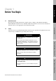
1.1 Before You Begin Chapter 1 Before You Begin About this manual This instruction manual explains how to install, start up, configure, and troubleshoot the Micro Motion IFT9701 transmitter for use with Micro Motion Coriolis flow sensors. For more information about the sensor, see the appropriate sensor instruction manual. Getting Started 1.2 Safety Safety messages are provided throughout this manual to protect personnel and equipment.
Before You Begin continued 1.3 European installations This Micro Motion product complies with all applicable European directives when properly installed in accordance with the instructions in this manual. Refer to the EC declaration of conformity for directives that apply to this product. The EC declaration of conformity, with all applicable European directives, and the complete ATEX Installation Drawings and Instructions are available on the internet at www.micromotion.
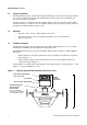
Before You Begin continued Figure 1-2 Remotely mounted IFT9701 transmitter Before You Begin Model IFT9701 transmitter Field wiring compartment With optional LCD Circuit board compartment User access not normally required Sensor wiring compartment Mounting bracket Requires 4 user-supplied bolts Cable gland • To assemble, see instructions shipped with cable kit • Connects to sensor junction box Getting Started 4X M8 mounting bolt • 4X lock washer • 4X flat washer To rotate transmitter: remove, then r
4 Model IFT9701 Transmitter Instruction Manual
2.1 Before You Begin Chapter 2 Getting Started Safety, reliability, accessibility WARNING Improper installation in a hazardous area could cause an explosion. Getting Started Install the transmitter in an environment that is compatible with the hazardous area specified on the approvals tag. • • Hazardous area If you plan to mount the transmitter in a hazardous area, ensure that your equipment and installation meet the hazardous area requirements.
Getting Started continued Figure 2-1 Location of approvals tag Hazardous area approvals tag 2.1.2 Orientation and mounting Orient the transmitter so wiring compartments and conduit openings are easily accessible. • To rotate the transmitter on the sensor manifold or the mounting bracket, use the four supplied mounting bolt assemblies. Each bolt assembly includes one M8 bolt, one lock washer, and one flat washer.
Getting Started continued 2.1.4 Visibility of tags 2.2 Transmitters approved for ATEX Zone 1 Before You Begin For personal and system safety, all tags attached to the transmitter housing must remain visible. Clean or replace them as necessary. WARNING Explosion hazard The circuit board compartment is rated EEx d (flameproof), and should remain closed at all times after the flowmeter has been installed.
Getting Started continued Figure 2-2 Compartment tags and lockout device Circuit board compartment Rated EEx d Field wiring compartment Rated EEx e Label 1 Label 2 Sensor wiring compartment Rated EEx i Lockout device Loosen and rotate before opening circuit board compartment 2.3 Jumper settings Unless otherwise specified on the order, jumpers are set so the transmitter generates downscale fault outputs and enables flowmeter configuration.
Getting Started continued 2.3.1 Security • With the security jumper OFF, the flowmeter configuration can be changed. • With the security jumper ON, the flowmeter configuration cannot be changed. Before You Begin The security jumper enables the user to write-protect the flowmeter configuration, so it cannot be changed using a HART communication device: The default setting is OFF. To set the security jumper, see Figure 2-3. 2.3.
Getting Started continued 2.3.3 Re-installing the circuit board compartment cover To re-install the cover of the circuit board compartment: 1. Screw the cover back onto the housing. 2. Hand-tighten the cover until it seats on the O-ring. 3. If the circuit board compartment has a lockout device, as shown in Figure 2-2, rotate the clamp into place and push it into the slot. Use a 4-mm (5/32-inch) Allen wrench to tighten the lockout screw to 5 inch-pounds (0,56 N-m) of torque.
Before You Begin Chapter 3 Remotely Mounting the Transmitter Note: The instructions in this chapter apply only if the transmitter will be remotely mounted from the sensor. If the transmitter is integrally mounted to the sensor, proceed to Chapter 4. 3.1 Overview 3.2 • Choosing the proper location (see Section 3.2) • Mounting the sensor on a flat surface or instrument pole (see Section 3.3) • Connecting the transmitter to the sensor (see Section 3.
Remotely Mounting the Transmitter continued Figure 3-1 Installation dimensions for remote mounting Dimensions in inches (mm) 5 3/4 (146) 3/4″–14 NPT or M20 X 1.5 for output wiring 3/4″–14 NPT or M20 X 1.
Remotely Mounting the Transmitter continued Figure 3-2 Mounting the transmitter to a wall or other surface Before You Begin Circuit board compartment User access not normally required Area approvals tag Field wiring compartment Sensor wiring compartment 4X M8 bolt 4X lock washer 4X flat washer To rotate transmitter: remove, then re-install to 12 ft-lb (16 N-m) torque Getting Started 4X 5/16 (M8) bolt User-supplied Figure 3-3 Mounting the transmitter to an instrument pole Area approvals tag Mounting
Remotely Mounting the Transmitter continued 3.4 Connecting the transmitter to the sensor CAUTION Improper installation of cable, cable gland, or conduit could cause inaccurate measurements or flowmeter failure. To ensure 360° termination shielding for flowmeter wiring, install the factory-supplied cable gland or user-supplied sealed metallic conduit to the conduit opening on the sensor junction box. To connect the transmitter to the sensor: • Micro Motion 9-wire cable is required. See Section 3.4.
Remotely Mounting the Transmitter continued Figure 3-5 Shielded cable Before You Begin Minimum bend radii Outer jacket Tin-plated copper braided shield Foil shield (1) Jacket material Inner jacket PVC Teflon® FEP Drain wire (4) Outside diameter Static (no load) condition Under dynamic load inches (mm) 0.525 (14) 0.
Remotely Mounting the Transmitter continued 3.4.2 Guidelines for conduit If sealed metallic conduit is installed, it must provide 360° termination shielding for the enclosed flowmeter cable. 1. Install a drip leg in conduit to prevent liquids from entering the junction box. 2. Connect the sealed end of the conduit to the ¾-inch NPT female conduit opening on the sensor junction box. 3.4.3 Guidelines for cable gland 1.
Remotely Mounting the Transmitter continued Figure 3-7 Cable connections to sensors Flowmeter cable Before You Begin ELITE and F-Series sensor terminals IFT9701 terminals Maximum cable length 1000 ft.
Remotely Mounting the Transmitter continued Figure 3-8 Sensor wiring compartment and sensor wiring terminals Sensor wiring terminals Sensor wiring compartment 18 Model IFT9701 Transmitter Instruction Manual
4.1 Before You Begin Chapter 4 Power Supply and Output Wiring Overview To wire the transmitter power supply and outputs: Review the wiring guidelines (see Section 4.2) • Connect the power supply wiring (see Section 4.3) • Connect the output wiring (see Section 4.4) Getting Started 4.2 • Wiring guidelines • Install cable and wiring so they meet local code requirements.
Power Supply and Output Wiring continued 4.3 Connect power supply wiring CAUTION Incorrect voltage, or installation with power supply on, could cause transmitter damage or failure. • • Figure 4-1 Match power supply voltage with voltage indicated on label in field wiring compartment. Shut off power before installing transmitter. • Figure 4-1 shows the power supply wiring terminals. • Wiring terminals accommodate 20 AWG (0,5 mm²) to 16 AWG (1,5 mm²) wire.
Power Supply and Output Wiring continued Table 4-1 Wire size Wire length 16 AWG (1,5 mm²) 1500 feet (450 meters) 18 AWG (0,75 mm²) 1000 feet (300 meters) 20 AWG (0,5 mm²) 600 feet (200 meters) Before You Begin 4.4 Wire guidelines for DC power supply Connect output wiring Figure 4-2 shows the milliamp and pulse output terminals. • Install twisted-pair, shielded cable, consisting of 20 AWG (0,5 mm²) to 16 AWG (1,5 mm²) wire. • For basic information on milliamp output wiring, see Section 4.4.1.
Power Supply and Output Wiring continued 4.4.1 Milliamp output The 4–20 mA output is an active output that can represent the mass or volume flow rate. At the factory, the output is configured to represent the range of flow rates that are measured in the application. The milliamp output is active, does not require external power, and has the following features: • Can supply any loop-powered process indicator. • Isolated to ±500 VDC from all other outputs and earth ground.
Power Supply and Output Wiring continued 4.4.2 Milliamp output connected to Bell 202 multidrop network Other Rosemount SMART FAMILY transmitters can also participate in a HART-compatible network. • A Bell 202 multidrop network uses twisted-pair wire, and allows only digital communication. • A HART Communicator or other HART-compatible control system can communicate with any device in the network over the same 2-wire pair.
Power Supply and Output Wiring continued 4.4.3 Communication tools connected to milliamp output ProLink II software from Micro Motion, AMS software from Emerson Process Management, or a HART Communicator can be connected to the flowmeter’s milliamp output. To connect using ProLink II, follow the instructions in the ProLink II manual. The AMS interface is similar to the ProLink II interface. See the AMS manual for AMS-specific information.
Power Supply and Output Wiring continued 4.4.4 Pulse output • The pulse output is galvanically isolated to ±500 VDC from the rest of the flowmeter. • When connected to the Series 3000 applications platform, the pulse output does not require an external power source. Otherwise, the pulse output requires a 5–30 VDC power source. • In the ON state, voltage will be less than 1 V.
Power Supply and Output Wiring continued Figure 4-6 Wiring to pulse counter with internal pull-up resistor Pulse counter with pull-up to internal power Input Ground (–) Frequency in (+) IFT9701 pulse output terminals Figure 4-7 Wiring to pulse counter without internal pull-up resistor Pulse counter with no pull-up Input Ground (–) Frequency in (+) External 5–30 VDC power supply Pull-up resistor To determine the value of the pull-up resistor, see the graph earlier in this section.
Power Supply and Output Wiring continued Figure 4-8 Wiring to Series 3000 applications platform with I/O cable Before You Begin IFT9701 pulse output terminals Series 3000 I/O cable terminals See Note 2 Earth ground (1) Paired cables with shield. Maximum length is 50 feet for 28 AWG wire (15 meters for 0,1 mm² wire), 500 feet for 22 AWG wire (150 meters for 0,3 mm2 wire). (2) Do not connect shields at this end.
28 Model IFT9701 Transmitter Instruction Manual
5.1 Flowmeter Startup Chapter 5 Flowmeter Startup Overview 5.2 Customer service The Micro Motion Customer Service Department is available for assistance with flowmeter startup if you experience problems you cannot solve on your own. If possible, provide us with the model numbers and/or serial numbers of your Micro Motion equipment, which will assist us in answering your questions. Phone numbers are listed on the title page of this manual. 5.
Flowmeter Startup continued 5.4 Initialization After wiring has been connected, power can be supplied to the flowmeter. During initialization, the flowmeter remains in startup mode for 13 to 40 seconds, depending on the sensor. 5.4.1 Diagnostic LED The diagnostic LED, shown in Figure 5-1, indicates the operating condition of the flowmeter. 5.4.2 Optional display Except for ATEX Zone 1 areas, the transmitter is available with an optional display. See Figure 5-1.
Flowmeter Startup continued Figure 5-1 Location of LED, zero button, and LCD Flowmeter Startup Circuit board compartment User access not normally required Area approvals tag Field wiring compartment With optional LCD Configuration with Communicator Sensor wiring compartment Zero button Diagnostic LED 5.5 Flowmeter zeroing After the flowmeter has been fully installed, you must perform the zeroing procedure.
Flowmeter Startup continued 3. Fill the flowmeter completely with the process fluid under normal process conditions of temperature, density, pressure, etc., and ensure zero flow through the flowmeter. 4. Make sure flow through the meter is completely stopped, then press and hold the zero button until the LED remains on continuously. See Figure 5-1. To end the zero operation before its completion, cycle power to the flowmeter.
Flowmeter Startup continued 5.7 Process measurement Flowmeter Startup After flowmeter zeroing has been completed, the flowmeter is ready for process measurement. WARNING Operating flowmeter without compartment covers in place exposes electrical hazards that can cause property damage, injury, or death. Ensure all housing covers are tightly closed and fully sealed before operating the flowmeter.
34 Model IFT9701 Transmitter Instruction Manual
6.1 Flowmeter Startup Chapter 6 Configuration with a HART Communicator Configuration overview Configuration parameters include such items as flow cutoff and damping values, flow direction, and milliamp output scaling. If requested at time of order, the meter is configured at the factory according to customer specifications. For factory-calibrated sensors, field calibration is not normally needed nor recommended. Basic configuration is described in Section 6.2.
Configuration with a HART Communicator continued 6.
Configuration with a HART Communicator continued Flowmeter Startup 4. Measurement units affect other field device variables, and must be sent (downloaded) to the flowmeter before other variables can be configured: a. Whenever the display below appears, press F4 (OK). b. To send the measurement unit to the flowmeter, press F2 (send).
Configuration with a HART Communicator continued 7. At the detailed setup menu, choose 2 (configure field device variables). 8. At the configure field device variables menu, choose 3 (temperature unit). 9. Repeat steps 5 and 6 to choose and enter a temperature unit. 6.2.3 Flow cutoff In some sensor installations, noise caused by mechanical sources, such as valves and motors, can affect flowmeter output signals.
Configuration with a HART Communicator continued To enter an internal damping value, use the menu below and follow these steps: Process variables Diag/service Basic setup DETAILED SETUP Review 1 Charize sensor 2 CONFIG FLD DEV VAR 3 Config outputs 4 Device 1 FLOW 2 Density 3 Temp unit 1 2 3 4 Flowmeter Startup 1 2 3 4 5 Flo unit Flo cutoff Flo direction FLOW DAMPING 1. At the online menu, choose 4 (detailed setup). 2. At the detailed setup menu, choose 2 (configure field device variables). 3.
Configuration with a HART Communicator continued 6.2.6 Range values for milliamp output Range values are the flow rates represented by the milliamp output at 4 mA and at 20 mA. To set range values, use the menu below and follow these steps: 1 2 3 4 5 Process variables Diag/service BASIC SETUP Detailed setup Review 1 2 3 4 5 Tag PV unit ANALOG RANGE VALS Freq factr Rate factr 1 PV URV 2 PV LRV 1. At the online menu, choose 3 (basic setup). 2. At the basic setup menu, choose 3 (analog range values).
Configuration with a HART Communicator continued 6.3 Calibration procedures Flowmeter Startup Calibration procedures include zeroing and flow calibration. 6.3.1 Auto zero Flowmeter zeroing establishes flowmeter response to zero flow and establishes a baseline for flow measurement. CAUTION Failure to zero the flowmeter at initial startup could cause measurement error. Configuration with Communicator Zero the flowmeter before putting the flowmeter into operation.
Configuration with a HART Communicator continued d. When the display reads “WARN Loop should be removed from automatic control”, isolate the flowmeter from devices that use flowmeter outputs to control the process, then choose F4 (OK). e. When the display reads “Flow must be zero, perform calibration?”, make sure flow through the sensor is completely stopped, then press F4 (OK). f. - The HART Communicator display reads “Calibration in progress” to indicate flowmeter zeroing in progress.
Configuration with a HART Communicator continued To calculate the flow calibration factor: Flowmeter Startup 1. Select a mass flow unit, and send the unit to the flowmeter memory. See Table 6-1. 2. To enter the flow calibration factor into flowmeter memory, refer to the menu below and follow these steps: 1 2 3 4 5 Process variables Diag/service Basic setup DETAILED SETUP Review 1 2 3 4 CHARIZE SENSOR Config fld dev var Config outputs Device information 1 FLOW CAL 2 Density cal factr a.
Configuration with a HART Communicator continued 6. Multiply the meter factor from Step 5 by the first five digits of the current flow calibration factor. This is the first five digits of the new flow calibration factor. First 5 digits of new FloCal factor 7.
7.1 Flowmeter Startup Chapter 7 Configuration with ProLink II Software Configuration overview Configuration parameters include such items as flow cutoff and damping values, flow direction, and milliamp output scaling. If requested at time of order, the meter is configured at the factory according to customer specifications. For factory-calibrated sensors, field calibration is not normally needed nor recommended. Basic configuration is described in Section 7.2.1.
Configuration with ProLink II Software continued 7.2 Configuration parameters Use the Configuration window to perform the following tasks: • Assigning a HART tag to the flowmeter • Changing process variable measurement: - Changing measurement units for the mass flow or volume flow rate - Changing the flow cutoff value - Changing the internal damping value - Changing the flow direction parameter • Setting range values for the milliamp output • Scaling the pulse output 7.2.
Configuration with ProLink II Software continued 7.2.2 Process variable measurement Flowmeter Startup To configure process variable measurement: 1. From the ProLink menu, click on Configuration. 2. In the Configuration window, click on the Flow tab. The Flow panel appers (as depicted in Figure 7-2). Figure 7-2 Configuration window – Flow panel Configuration with Communicator Configuration with ProLink II 3. To specify the flow measurement unit, open the Flow Units list box and select a flow unit.
Configuration with ProLink II Software continued Table 7-1 Measurement units for mass and volume flow Mass flow unit Software label Volume flow unit Software label grams/second grams/minute grams/hour kilograms/second kilograms/minute kilograms/hour kilograms/day metric tonnes (1000 kg)/minute metric tonnes (1000 kg)/hour metric tonnes (1000 kg)/day pounds/second pounds/minute pounds/hour pounds/day short tons (2000 pounds)/minute short tons (2000 pounds)/hour short tons (2000 pounds)/day g/s g/min
Configuration with ProLink II Software continued Table 7-2 Effect of flow direction on outputs and totalizers Output or totalizer Fluid flowing in same direction as flow arrow on sensor Flowmeter configuration Forward Reverse Milliamp output Output increases as flow rate increases Output goes to 3.8 mA Pulse output Output increases as flow rate increases Output remains at 0 Hz Internal totalizers Flow totals increase Flow totals remain constant Milliamp output Output goes to 3.
Configuration with ProLink II Software continued 7.2.3 Output configuration Basic configuration of flowmeter outputs includes: • Setting range values for the milliamp output. • Scaling the pulse output. To configure the milliamp output: 1. From the ProLink menu, click on Configuration. 2. Click on the Analog Output tab. The Analog Output panel appears, as shown in Figure 7-3. Figure 7-3 Configuration window – Analog Output panel 3.
Configuration with ProLink II Software continued To configure the pulse output: Flowmeter Startup 1. From the ProLink menu, click on Configuration. 2. Click on the Frequency tab. The Frequency panel appears, as shown in Figure 7-3. Figure 7-4 Configuration window – Frequency panel Configuration with Communicator a. In the text box labeled Freq Factor, enter a value for the frequency in pulses per second (Hertz) that corresponds to the maximum flow rate. b.
Configuration with ProLink II Software continued CAUTION Failure to zero the flowmeter at initial startup could cause measurement error. Zero the flowmeter before putting the flowmeter into operation. To perform the auto zero procedure: 1. Prepare the flowmeter for zeroing: a. Install the flowmeter according to the instructions in this manual. b. Apply power to the meter, then allow it to warm up for at least 30 minutes. c.
Configuration with ProLink II Software continued Figure 7-5 Flow Calibration dialog box Flowmeter Startup Configuration with Communicator Diagnosing zeroing failure If zeroing fails: The Calibration Failure status light turns red. • The meter’s diagnostic LED blinks ON four times per second. • The flowmeter produces fault outputs. • The message “ELEC0” blinks on and off in the meter’s optional display.
Configuration with ProLink II Software continued Use a mass flow unit during the calibration procedure. If the application requires volume flow measurement, choose a mass flow unit for the flow calibration, then choose a volume flow unit for the application. To calculate the flow calibration factor: 1. Configure the transmitter to use a mass flow measurement unit (see Section 7.2.2). 2.
Configuration with ProLink II Software continued Weightscale Flowmeter Startup 6. Run three batches of fluid, resetting the scale and totalizer between batches. For each batch, record the weights indicated by the scale and the totalizer. Weighttotalizer First batch Second batch Third batch Total Configuration with Communicator 7. Divide Total Weightscale by Total Weighttotalizer. This is the mass-flow meter factor. Record the meter factor. Mass-flow meter factor 8.
Configuration with ProLink II Software continued Figure 7-7 56 Configuration window – Density panel Model IFT9701 Transmitter Instruction Manual
8.1 Flowmeter Startup Chapter 8 Troubleshooting Customer service 8.2 General guidelines Troubleshooting a Micro Motion flowmeter is performed in two parts: • Tests of wiring circuit integrity. • Observation of the transmitter's diagnostic tools, which include the diagnostic LED, fault output levels, and optional LCD. CAUTION Configuration with Communicator For assistance, phone the Micro Motion Customer Service Department. Phone numbers are listed on the title page of this manual.
Troubleshooting continued Figure 8-1 Transmitter terminals and diagnostic LED Milliamp output terminals Power supply • If transmitter fails to produce outputs, check for reversed polarity • Make sure actual power supply matches power supply shown on label • AC power applied to DC transmitter will damage transmitter • Power-supply fuses are not replaceable Pulse output terminals – + 20–30V or N L 85–250V~ Intrinsically safe terminal block Sensor wiring compartment (intrinsically safe) Ground screw for
Troubleshooting continued Table 8-2 Conditions indicated by optional LCD Mass or volume flow rate (such as “100.00”) Normal operation “OL0” Flow rate has exceeded upper limit of display “ 88.8.8.
Troubleshooting continued Figure 8-2 Power supply connections ¾-inch NPT or M20 conduit opening Seal opening with conduit seal or cable gland Power supply terminals External case ground screw Internal ground screw Voltage label Match power supply to voltage specified on label 7. Make sure the power cable is not installed in the same conduit or cable tray as output wiring. 8. Make sure the meter is properly grounded.
Troubleshooting continued Table 8-3 Sensor terminal designations Function 1 Brown Drive + 2 Red Drive – 3 Orange Temperature – 4 Yellow Temperature lead length compensator 5 Green Left pickoff + 6 Blue Right pickoff + 7 Violet Temperature + 8 Gray Right pickoff – 9 White Left pickoff – To check integrity of sensor wiring circuits: 1. Disconnect the transmitter's power supply. 2.
Troubleshooting continued If the transmitter indicates an over range or sensor failure condition, follow these steps: 1. Isolate the transmitter from devices that use transmitter outputs to control the flow loop. 2. Refer to Table 8-5 to diagnose the problem. 3. If troubleshooting fails to reveal why over range and/or sensor failure messages have appeared, phone Micro Motion Customer Service. Phone numbers are listed on the title page of this manual.
Troubleshooting continued A slug flow condition causes the following to occur: The pulse output goes to 0 Hz. • The milliamp output goes to the level that represents zero flow. • The diagnostic LED blinks OFF once per second. • The optional LCD reads “SLUG0”. Flowmeter Startup • The flowmeter resumes normal operation when density stabilizes within the programmed slug flow limits. 8.
64 Model IFT9701 Transmitter Instruction Manual
A.1 Specifications Appendix A IFT9701 Specifications Performance specifications For performance specifications, refer to the documentation for your sensor. A.2 Functional specifications HART Menu Trees A.2.1 Output signals Milliamp (active) • 4–20 mA output represents mass flow or volume flow • Sensor size determines minimum and maximum spans. Recommended minimum span (% of nominal flow range): - ELITE sensors: 2.
IFT9701 Specifications continued A.2.2 Local display (optional) 5-digit, alphanumeric, liquid crystal display (LCD) installed on the field-wiring compartment cover. The LCD shows flow rate, and indicates slug flow, flowmeter zeroing in progress, and electronic faults. Note: Not available for ATEX Zone 1 applications. A.2.3 Low-flow cutoff Flow rate below cutoff causes outputs to default to level that indicates zero flow and totalizer stops counting A.2.
IFT9701 Specifications continued 20 to 30 VDC 6 watts typical, 14 watts maximum • Fused at 60 V/1.8 A Trip • Minimum startup voltage is 16 V at transmitter terminals • Maximum total resistance for wiring is 13 ohms • At startup, transmitter power source must provide a minimum of 0.7 amp of short-term current Specifications A.3 • Environmental limits A.3.1 Temperature Operating HART Menu Trees See Process fluid vs.
IFT9701 Specifications continued 150 Maximum, with no external heat source Expected maximum ambient temperature, °F 140 130 120 110 100 Maximum, when mounted in direct sunlight 90 80 70 158 167 176 185 194 203 212 221 230 239 248 257 266 Process fluid temperature, °F Expected maximum ambient temperature, °C 60 55 Maximum, with no external heat source 50 45 Maximum, when mounted in direct sunlight 40 35 30 70 75 80 85 90 95 100 105 110 115 120 125 130 Process fluid temperature, °C A.3.
IFT9701 Specifications continued A.5 Environmental effects To meet the above specifications, the transmitter must be installed with an approved Micro Motion sensor, and the sensor cable must be doubly shielded with full-contact glands, or installed in continuous, fully bonded metallic conduit. The transmitter and sensor must be directly connected to a low-impedance (less than 1 ohm) earth ground. Transmitter outputs must be standard twisted-pair, shielded instrument wire. A.
70 Model IFT9701 Transmitter Instruction Manual
Specifications Appendix B HART Communicator Menu Trees Online Menu 1 PROCESS VARIABLES 1 VIEW FIELD DEVICE VARIABLES Flow Temperature Total Density 1 PV 2 PV % rng 3 PV AO 1 VIEW PRIMARY VARIABLE 2 View secondary variable 1 TV 2 Pres freq 3 VIEW TERTIARY VARIABLE 3 View status 4 TOTALIZER CONTROL 2 DIAGNOSTCS AND SERVICE 1 TEST/STATUS 4 View quaternary variable 1 Total 2 Reset totalizer 1 View status 2 Self test 1 2 3 4 3 Basic setup* 4 Detailed setup* 5 Review* 4 mA 20 mA Other End 2 FIX FR
HART Communicator Menu Trees continued Online Menu 1 Process variables* 2 Diagnostics and service* 3 BASIC SETUP 1 2 3 4 5 Tag Primary variable unit ANALOG RANGE VALUES Frequency factor Rate factor 1 CHARACTERIZE SENSOR 1 Upper range value 2 Primary variable lower range value 1 Flow calibration factor 2 Density calibration factor 1 FLOW 1 2 3 4 2 CONFIGURE FIELD DEVICE VARIABLES 1 Density unit 2 Slug flow low limit 3 Slug flow high limit 2 DENSITY 4 DETAILED SETUP Flow unit Flow cutoff Flow dire
Specifications Appendix C Installing the Optional Display WARNING Line voltage can cause electric shock or transmitter damage. HART Menu Trees Disconnect input power before installing display. To install the optional display, follow these steps: 1. Make sure you are wearing an anti-static wrist strap. 2. Disconnect input power to the flowmeter. 3. Loosen the captive screws that hold the field wiring compartment cover in place, then remove the cover. 4.
Installing the Optional Display continued 8. Put the retaining clip, washer, and screw in place on the back of the display. See illustration, below. Back of display Retaining clip 9. Put the display in place on the field wiring compartment. Tighten the screws evenly until the display assembly is flush against the flowmeter housing and is completely sealed. CAUTION Failure to seal flowmeter housing could cause a short circuit, which would result in measurement error or flowmeter failure.
D.1 Specifications Appendix D Return Policy General guidelines Micro Motion procedures must be followed when returning equipment. These procedures ensure legal compliance with government transportation agencies and help provide a safe working environment for Micro Motion employees. Failure to follow Micro Motion procedures will result in your equipment being refused delivery. HART Menu Trees Information on return procedures and forms is available on our Web support system at www.micromotion.
76 Model IFT9701 Transmitter Instruction Manual
Index Index A About this manual 1 Accessibility, reliability and safety 5–7 Agency approvals approved areas 69 hazardous area installation 5 Approvals tag 7 Armored cable bend radii 15 cable types 14 conduit requirements 15 temperature limits 15 ATEX approved areas 69 hazardous area installation 5 Zone 1 installation 7 B Before you begin 1–3 Bell 202 multidrop network 23 network wiring 23 C Cable bend radii 14, 15 conduit installation guidelines 16 requirements 15 gland installation guidelines 16 sensor wi
Index continued Definitions 2 Density calibration factor HART Communicator 44 ProLink II software 55 Diagnostic LED startup 30 troubleshooting with 57 Display diagnostic messages 63 installing 73–74 specifications 65 startup 30 troubleshooting with 58 E Environmental effects 68 F Fault outputs jumper settings 9 specifications 66 troubleshooting with 58 Flow calibration factor HART Communicator 42 ProLink II software 53 Flow direction configuration HART Communicator 39 ProLink II software 48 Flowmeter compo
Index continued P Power supply specifications 66 troubleshooting 59 wiring 19 ProLink II software configuration 45 output specifications 65 wiring connections 24 Pulse counter wiring 25 Pulse output specifications 65, 66 R Reliability, safety and accessibility 5–7 Return policy 75 S Safety, reliability and accessibility 5–7 Security jumper settings 9 Sensor compatibility 2 definition 2 failure condition 61 Series 3000 platform pulse output 25 Shielded cable bend radii 15 cable types 14 conduit requirements
Index continued U UL approved areas 69 hazardous area installation 5 Used equipment returns 75 V Vibration limits 68 installation 6 W Wiring 19 CE requirement 20 general guidelines 19 grounding 20 outputs 21–23 HART Communicator 24 HART network 23 milliamp output 22 ProLink II software 24 power supply 19, 20 resistance 61 sensor connections 16 terminal designations 17 troubleshooting 60–61 voltage 61 Z Zeroing 31–32 failure HART Communicator 42 ProLink II software 53 startup 32 HART Communicator 41–42 ProL
©2004, Micro Motion, Inc. All rights reserved. P/N 3100572, Rev. E *3100572* For the latest Micro Motion product specifications, view the PRODUCTS section of our Web site at www.micromotion.com Micro Motion Inc.