026-1727 Rev 0 11-APR-2011 iPro DAC Installation and Operation Manual
Retail Solutions 3240 Town Point Drive NW, Suite 100 Kennesaw, GA 30144 Phone: 770-425-2724 Fax: 770-425-9319 ALL RIGHTS RESERVED. The information contained in this manual has been carefully checked and is believed to be accurate. However, Computer Process Controls, Inc. assumes no responsibility for any inaccuracies that may be contained herein. In no event will Computer Process Controls, Inc.
Table Of Contents 1 INTRODUCTION.......................................................................................................................................................... 1 1.1. THE IPRO DAC’S I/O POINTS ....................................................................................................................................... 1 1.2. INDEPENDENT SYSTEM CONTROL ..........................................................................................................................
.5. FAN CONTROL ............................................................................................................................................................ 16 6.5.1. CAV Mode ........................................................................................................................................................... 16 6.5.1.1. Variable-Speed Fan Control in CAV......................................................................................................................
9.2.3. Analog Outputs ................................................................................................................................................... 9.2.4. Digital Inputs ...................................................................................................................................................... 9.3. RELAY OUTPUT OVERRIDES WITH VISOGRAPH.......................................................................................................... 9.3.1.
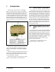
1 Introduction The iPro DAC (P/N 818-9001) is a packaged HVAC control board for use either as a standalone controller or in zone control applications using a Retail Solutions E2 BX building control system. The iPro DAC is capable of controlling heat and cool stages, fans, dehumidification devices, and economizers using on-board I/O and control algorithms, as well as monitor and interact with other building control systems and peripherals (such as smoke alarms and CO2 sensors). 1.1.
2 Mounting and Powering The iPro DAC is usually mounted by the HVAC equipment manufacturer. Therefore, the installer need only make the necessary connections between the boards and the site controller(s). In some instances, an installer may be required to mount the iPro DAC. There are no restrictions on the location of the iPro DAC; however, the controller should be mounted in a location protected from moisture. Typically, mounting inside the electrical control panel of a package unit is acceptable.
Neither side of the secondary should be connected to ground. Also, do not connect the center tap (if provided on the transformer) to ground. The entire secondary of the transformer should be isolated from any ground. Use these formulas to determine if the wire gauge you are using fits within specification: 14 AWG: Feet = 1920/VA 18 AWG: Feet = 739/VA (VA is the total VA rating of the controller) For example, if you had an 80 VA load: 14 AWG: 24 ft. 18 AWG: 9 ft.
3 The MODBUS Network Although the iPro DAC can operate as a standalone controller, it relies on an E2 unit for advanced features such as remote dial-in/dial-out, logging, and alarm control. The iPro DAC uses an RS485 network connection to communicate with E2 site controllers. If the recommended cable is not available in your area, be sure the wiring meets or exceeds the following specs: Yes Shielded? Conductor Type Twisted Pair Gauge 18 - 24 AWG 3.1.
3.1.2. Network Addressing - Visograph The network address makes a board unique from other boards on the network of the same type. This allows the site controller to find it and communicate with it easily. The network address of the iPro DAC is set using add-on devices called visographs (P/N 318-7272). 3.1.2.1. Connecting the Visograph The visograph is connected with a 3-wire connection on pins 103, 104, and 105. Figure 3-3 - Visograph Buttons 3.1.2.3.
should start blinking. 3. Using the UP and DOWN arrows (T4 and T5), change the address to the desired value. 4. Press ENTER to save new address.The address field should stop blinking. 5. Press MENU (T1) to go back to main menu. NOTE: When the MODBUS address is changed, the iPro DAC will automatically reboot. 3.1.2.3.1. Versions The iPro DAC and Visograph versions are also shown on the Controller Info screen. If the Visograph version shown is not the most recent, set the Reload Display field to Yes.
4 Input and Output Setup 4.1.
4.1.1. Wiring Analog Inputs on the iPro DAC The analog inputs are located on the same connector as the controller power supply. CAUTION! Any inputs that are powered with a voltage that differs from that supplied by the iPro DAC (+12V or +5V) must be powered separately with another transformer in order to prevent the inputs from malfunctioning or being damaged. Do not use the same secondary of the controller's power to power the sensors.
The iPro DAC provides a maximum of 20 opto-insulated digital inputs. However, only the first ten inputs are currently used (see Table 4-2). All digital inputs are voltage-free and are intended to have dry contact devices connected. 4.2. The iPro DAC Outputs Relay Outputs Figure 4-7 - Digital Input Wiring Analog Outputs Terminal Number on Connector Figure 4-8 - iPro DAC Output Locations Name The iPro DAC has 15 relay outputs for connection to all loads that are typically present for a rooftop unit.
The iPro DAC supports the following analog outputs: Analog Output Description Terminal Number on Connector Name Mod Fan (VS) Modulating Fan 70 Relay 1 Mod Cool (2) Modulating Cool Stages (including Digital Scroll compressors) 71 Common for Relays 1-3 72 Relay 2 Mod Heat Modulating Heat 73 Relay 3 Mod Outdoor Air Damper Modulating Outdoor Air Damper 76 Relay 4 Mod Return Air Bypass Modulating Return Air Bypass 77 Relay 5 Mod Return Air Damper Modulating Return Air Damper 78 Relay
used to power the devices controlled by the analog outputs (e.g., damper actuator) may be used to supply power to terminals 28 and 29. Figure 4-12 - Analog Output Wiring CAUTION! The devices controlled by these analog outputs must be powered separately with another transformer (do not use the same secondary of the controller’s power) in order to prevent the outputs from malfunctioning or being damaged.
5 iPro DAC Status LEDs When an iPro DAC board is powered up, you will be able to determine the operating status of the board by observing its status LEDs. Figure 5-1 -iPro DAC Status LED Locations 5.1. PWR ON LED 5.3. LED1 Network Status The PWR ON LED stays on continuously to show that the board is powered and operational. If this light is dark, the board has likely lost power. The Tx and Rx LEDs indicate when the iPro DAC is sending or receiving messages on the RS485 network.
6 Software Overview The iPro DAC maintains space temperature setpoints by modulating heating or cooling stages to maintain a desired supply air temperature. For this reason, a supply air temperature sensor must be connected to the controller. The desired supply air temperature is primarily determined by a setpoint and can be automatically adjusted based on changes in building load. 6.1.
terminal load can range from -100% to +100%, where all negative values indicate a demand for heating and all positive values indicate a demand for cooling. 6.4.2. Cooling Mode The iPro DAC supports both staged and modulating mechanical cooling devices. Modulating devices are treated as a cooling stage in the case of a unit having a mixture of fixed and variable capacity compressors. 6.4.2.1. Figure 6-1 - Terminal Load Graph When the terminal load rises above 20%, cooling mode will be activated.
ture is above the active supply air cooling setpoint. However, the next higher stage after a variable capacity stage will start its On-Delay only after the variable stage is at its maximum capacity. Likewise, the next lower stage before a variable capacity stage will start its Off-Delay only after the variable stage is at its minimum capacity. When a variable capacity compressor is activated, it will modulate to maintain the supply air temperature at the active supply air cooling setpoint.
less than 100%. When all primary heating stages have been activated, secondary heat stages will be allowed to stage on similar to the primary heating stages. the modulating heat output will turn off, leaving only the primary heat stages still active. The primary heat stages will then stage off as previously described. Secondary and primary heat stages will be sequentially turned off as demand for heating is reduced.
6.5.1.1. Variable-Speed Fan Control in CAV When using a variable-speed fan, each heat and cool stage has its own individual VS fan speed setpoint. When one or more stages are active, the iPro DAC will look at the setpoints of all active stages and operate the VS fan at the highest setpoint value. Example: An iPro DAC is controlling two heat stages. Heat stage #1’s VS fan setpoint is 50%, and Heat stage #2’s VS fan setpoint is 100%.
vice or activate stages of cooling up to a user-defined maximum number of cool stages to be used for dehumidification. A reheat output is also available for units equipped with hot gas reheat. Additionally, the unit’s primary heating outputs may be used to augment or replace the hot gas reheat function. 6.6.1. Enabling Dehumidification The iPro DAC can use several methods to determine if the controlled space requires dehumidification.
digital compressor has reached its maximum capacity, similar to how digital compressors stage up in cooling mode. Two suction pressure inputs are supported, so when the second digital compressor is activated, the controller will use the second suction pressure transducer to calculate the coil temperature. point. For example, if the RAB damper is at 50% and the RA damper multiplier is 10%, the RA damper will close an additional 5% from its current position. 6.6.3.
6.7.3. Economizer Control Economizer dampers on rooftop HVAC units are used to bring outside air into the building for use in cooling. The iPro DAC supports control of two-position outside air dampers as well as variable-position (analog) dampers. The iPro DAC controls economization by first determining whether the outside air conditions are favorable for bringing in outside air (see Section 6.7.3.3., Economization Enabling Strategy).
sensor fails, economization will be disabled. 5. E2 Zone Enable (BAS) – This method is always used when the iPro DAC is connected to the E2. The controller will read the value of the ECONOMIZATION output from the E2 zone and enable economization based on that value. The E2 zone must be programmed with its own method of economization checking (refer to the E2 user manual 026-1610 and on-line help for HVAC Zone application setup instructions). 6.7.4.
that if the supply temperature sensor fails, the unit will not be able to turn on any heating or cooling stages. This sensor must be repaired immediately. Control Temp Failure The preferred sensor to be used to control the space is user configured. By default, Space Temp 1 is the sensor used. However, Space Temp 2, the average of both Space Temps, Return Temp, calculated Apparent Temp or a Zone Temperature from the E2 can be selected as the primary control temperature.
7 E2 Setup 7.1. Network Connection to E2 The iPro DAC is capable of communicating with an E2 version 3.0 or above. E2 PIB COM PORT ASSOCIATIONS Using iPro DAC with a central E2 offers several benefits over simple standalone control, including: E2 Enclosure (Right Side) • Reporting of iPro DAC-related alarms in the Alarm Advisory Log. E2 Modem/Expansion COM Card Mounted Above PIB RS232 • The ability to log iPro DAC inputs in an E2 logging group.
nation jumpers to the TERMINATED & BIASED position (all three jumpers UP); otherwise, set all jumpers DOWN if not the first device. 7.1.1. Setup Network Ports Before setting up a iPro DAC, the port on the E2 that has the MODBUS cable connected must be set up as a MODBUS port. 1. Log in to the E2 with Level 4 access. 2. Press followed by - General Controller Info. 7.2. Add and Connect iPro DACs To enable communications between E2 and the iPro DAC units, the devices must be added and addressed in E2.
ing with iProDAC001. you set the address:. Figure 7-4 - Network Summary Screen 6. By default, each iProDAC’s board number in the network list is indicated by a - (dash). To set the address and begin communication, press to Commission. (If you have more than one MODBUS network, specify which network you want the device to belong to.) Figure 7-6 - Set the Address of the iPro DAC 8. When finished, press to return to the Network Setup menu, then press - Network Summary.
that has the latest version of firmware on it. Figure 7-7 - Network Summary Screen 7.3. Viewing the iPro DAC Status Screen Once you have added an iPro DAC to the E2, you will be able to see the status of the iPro DAC board(s) from the front panel. 1. From the Main Status Screen, press key and select - Configured Applications. 2. Select iProDAC from the menu. If multiple iPro DACs are associated with this E2, the iPro DAC Summary Screen will be shown.
8 Connections 8.1.
8.2. Terminal Number Descriptions Terminal No.
47 DI8 Opto-insulated digital input 8 48 DI9 Opto-insulated digital input 9 49 DI10 Opto-insulated digital input 10 50 GND(-) 51 DI11 Opto-insulated digital input 11 52 DI12 Opto-insulated digital input 12 53 DI13 Opto-insulated digital input 13 54 DI14 Opto-insulated digital input 14 55 DI15 Opto-insulated digital input 15 56 DI16 Opto-insulated digital input 16 57 DI17 Opto-insulated digital input 17 58 DI18 Opto-insulated digital input 18 59 DI19 Opto-insulated digita
94 RS485 Master RS485 Master connection (-) 95 RS485 Master RS485 Master connection (+) 96 RS485 Master RS485 Master connection (insulated gnd) 97 RS485 Slave RS485 Slave connection (-) 98 RS485 Slave RS485 Slave connection (+) 99 RS485 Slave RS485 Slave connection (insulated gnd) 100 CAN Bus CAN Bus connection (+), not open 101 CAN Bus CAN Bus connection (-), not open 102 CAN Bus CAN Bus connection (insulated gnd), not open 103 Remote Display Connection for VISOGRAPH remote ter
8.3. Technical Specifications 8.3.1. Analog Inputs 8.3.2.
8.3.4. Digital Outputs Type: Relays with NO contacts Number of outputs: 10 or 15, depending on the model Type of output: Relays with normally open contact (configurable via software parameter) Maximum load: 5A(250Vac) SPST 5(2)A Table 8-6 - Digital Outputs Specifications CAUTION! Verify the capacity of the output used. There is double insulation between the digital outputs and the low voltage of the rest of the circuit.
8.4.
9 Using the Visograph 9.1. Viewing Status For visograph button functionality, see Section 3.1.2.2., Visograph Navigation section. 9.1.1. Input Status 1. From the main menu, select 1 to navigate to the status screens Figure 9-2 - Status - Outputs 2. The status of the most common iPro DAC inputs are shown on this screen 9.1.3. VAV Fan Status 3. All temperature units are in °F. Suction pressures are shown in PSI.
Figure 9-4 - I/O Config - Analog Inputs Figure 9-6 - I/O Config - Analog Outputs 9.2.2. Relay Outputs 9.2.4. Digital Inputs 1. Press the RIGHT arrow to navigate to the relay outputs configuration screen. The current configuration of local relay outputs 1-10 are shown on this screen. 2. Press the RIGHT arrow to navigate to the digital inputs configuration screen. The configuration of all supported digital inputs are shown on this screen. All digital inputs are fixed in position and cannot be edited.
4. Use the UP and DOWN arrows (T4 and T5), to change the override state to the desired value. The choices are Auto, ON, and OFF. 5. Press ENTER to activate the new override state. 6. Press MENU to go back to main menu screen. Figure 9-9 - Overrides - Analog Outputs 9.3.1.1. 1. Use the UP and DOWN arrows to navigate to the desired analog output. 2. Press the ENTER key. The field will start blinking. 3. Use the UP and DOWN arrows (T4 and T5), to change the override to the desired voltage.
Index -AAddressing iPro DAC 5 Analog Inputs 7 Analog Outputs 10 Application Mode 13 AWG 3 -CCAV 13 CAV Mode 13 Connecting iPro DACs 24 Connections 27 Connector Functions 27 Cooling Mode 14 -DDaisy Chain Configuration 4 Dehumidification Control 17 Digital Inputs 8 Digital Loads 10 Digital Outputs 9 Digital Scroll 18 DIN Mounting 2 Distance of Wiring 3 -EE2 23 Add and Connect iPro DAC 24 Addressing 24 Setup Network Ports 24 E2 and iPro DAC 23 E2 Network Connection 23 E2 Setup 23 Economizer Control 20 -FFan Co
Analog Output Overrides 35, 36 Buttons 5 Clear Analog Output Override 36 Connectivity 5 Override Analog Output 36 Relay Output Overrides 35 VAV Fan Status 34 Viewing I/O Configuration 34 analog inputs 34 analog outputs 35 digital inputs 35 relay outputs 35 Viewing Status 34 input status 34 output status 34 Visograph Connectivity 5 -WWarnings Analog Inputs 8 Analog Outputs 10, 11 Output Capacity 32 Transformers 31 Voltages 32 Wire Length 3 Wire Distance 3 Wire Gauge/Types 3 Wiring 33 40 • iPro DAC Manual 0