
Specifications


10 • The iPro DAC Outputs 026-1727 Rev 0 11-APR-2011
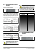
The iPro DAC supports the following analog out-
puts:
For both relay and analog outputs, the iPro DAC
will drive physical points as well as send the current
output value over Modbus to E2.
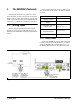
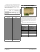
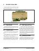
4.2.1. Wiring Digital Loads on the
iPro DAC
The digital output relays are located across four
separate connectors along the top side of the iPro
DAC.
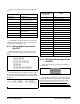
The normally-open relay outputs on each connec-
tor share the same common and are not fused. Make
sure to use the same voltage for all loads connected to
the relays.
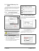
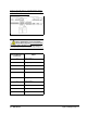
4.2.2. Wiring Analog Outputs on the
iPro DAC
The analog outputs are located on a separate 12-
pin connector.
The iPro DAC provides six opto-isolated analog
outputs. Because the analog outputs are opto-isolated,
they must be separately powered by a 24V supply.
For the outputs to function properly, connect a
24VAC supply (separate from the controller’s main
supply) to terminals 28 and 29. The same transformer
Analog Output Description
Mod Fan (VS) Modulating Fan
Mod Cool (2) Modulating Cool Stages (including
Digital Scroll compressors)
Mod Heat Modulating Heat
Mod Outdoor Air Damper Modulating Outdoor Air Damper
Mod Return Air Bypass Modulating Return Air Bypass
Mod Return Air Damper Modulating Return Air Damper
Mod VAV Bypass Damper Modulating Variable Air Volume
Bypass Damper
Supply Air SP Reset Supply Air Setpoint Reset
Auxiliary (2) Satellite Outputs Controlled by E2
Table 4-6 - iPro DAC Analog Outputs
Figure 4-9 - Digital Load Connectors
Figure 4-10 - Relay Output Wiring
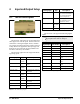
Terminal Number on
Connector
Name
70 Relay 1
71 Common for Relays 1-3
72 Relay 2
73 Relay 3
76 Relay 4
77 Relay 5
78 Relay 6
79 Relay 7
80 Common for Relays 4-8
81 Relay 8
84 Relay 9
85 Relay 10
86 Common for Relays 9-10
87 Relay 11
88 Relay 12
89 Relay 13
90 Common for Relays 11-15
91 Relay 14
92 Relay 15
93
Table 4-7 -Digital Relay Output Connector Terminal Numbers
Figure 4-11 - Analog Outputs Connectors