
Specifications
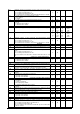


1592032000 iProCHILL_4DIN GB r.1.0 20.01.2012 iProCHILL 4 DIN series 43/48
Et12 Selection of output circuit valve 2 driver 2
0 = Not present
1 = Circuit 1
2 = Circuit 2
0 2
Et13
Et14
Et15
Et16
Et17 Number of additional steps to achieve complete closure. When a closing
request is received, the valve starts from the current number of steps and
moves to 0, then closes for the set number of steps
0 250
Et18 Number of return steps in opening mode after the valve has been closed
completely. These decompress any closing spring inside the valve or to
prevent sealing the circuit
0 250
Et19 Maximum number of adjusting steps of the valve Et20 8000
Et20 Minimum number of adjusting steps of the valve 0 Et19
Et21 Maximum current value per phase of the stepper motor 0 100 mA x10 mA
Et22 Current stand-by value 0 100 mA x10 mA
Et23 Maximum number of steps per second of the valve 0 600 Hz
Et24 Indicates the number of steps the valve has to move before compressor
start-up.
0 = function is disabled
0 Et19
Et25 Sets valve manual operation mode
0= Automatic
1= Manual
0 1
Et26 Absolute number of steps the valve has to move in manual mode 0 Et19
Et27 Low pressure alarm activation delay (LOP) 0 250 Sec
Et28 High pressure alarm activation delay (MOP) 0 250 Sec
Et29 High overheating alarm activation delay 0 250 Sec 10 Sec
Et30 Low overheating alarm activation delay 0 250 Sec 10 Sec
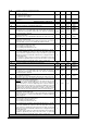
PID regulation in chiller mode
Et31 PID proportional constant in chiller mode 0.0
0
50.0
122
°C
°F
tenth
Whole
Et32 PID integral time in chiller mode
0 250 Sec
Et33 PID derivative constant in chiller mode
0 250 Sec
Et34 Overheating regulation set point during chiller mode 0.0
0
25.0
77
°C
°F
tenth
Whole
Et35 Overheating regulation dead band in chiller mode 0.0
0
5.0
41
°C
°F
tenth
Whole
Et36 High overheating threshold. The alarm status is signalled after the high
overheating alarm activation delay
Et34
80.0
176
°C
°F
tenth
Whole
Et37 Low overheating threshold. In this case, an additional integral time is
added to the normal regulation in order to speed up the return to the
normal operating conditions
0.0
0
Et34
°C
°F
tenth
Whole
Et38 Additional integral time to prevent low overheating in chiller mode 0 250 Sec
Et39 MOP protection activation threshold.
This sets the high pressure protection intervention threshold, above
which an additional regulation is activated, similar to that of low
overheating mode.
0.0
0
50.0
725
bar
psi
tenth
Whole
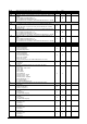
Et40 Pressure set point used during PI function in MOP 0.0
0
50.0
725
bar
psi
tenth
Whole
Et41 Proportional part of the PI in MOP regulation 0.0
0
50.0
725
bar
psi
tenth
whole
Et42 Integral time for MOP protection
0 250 Sec
Et43 LOP protection activation threshold.
This sets the low pressure protection intervention threshold, below which
an additional regulation is activated, similar to that of low overheating
operation.
0.0
0
50.0
725
bar
psi
tenth
Whole
Et44 Pressure set point used during operation in LOP of PI 0.0
0
50.0
725
bar
psi
tenth
Whole
Et45 Proportional part of the PI in LOP regulation 0.0
0
50.0
725
bar
psi
tenth
Whole
Et46 Integral time for LOP protection 0 250 Sec
Et47 Waiting time for machine start up before MOP chiller alarm signal 0 250 Sec
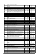
PID regulation in Heat pump mode
Et48 PID proportional constant in heat pump mode 0.0
0
50.0
122
°C
°F
tenth
Whole
Et49 PID integral time in heat pump mode
0 250 Sec
Et50 PID derivative constant in heat pump mode
0 250 Sec
Et51 Overheating regulation set point in heat pump mode
0.0
0
25.0
77
°C
°F
tenth
Whole