
User Guide
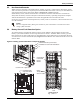

Battery Installation
Liebert
®
APM
™
56
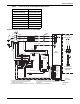
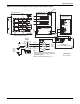
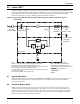
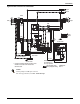
Figure 42 Control wiring diagram for battery ground fault detection option
UAM04050B
Pg. 2, Rev. 0
Notes
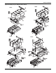
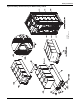
1. All battery service and initial connections
must be performed by properly trained and
qualified personnel.
2. Refer to drawing # UAM04050A, Pg. 1.
UHRF3S67X2 (J9)
UHR93S6A1ZA6
Output EMI Board
UHW241M5
Auxiliary Power Board
ULC366SC1
Ground Fault Detect Board
Liebert APM Bypass Module
Battery
Breaker
W601
W602
W600
W603
Red
Red
X2_J4
X2_J9
Blk
Blk
Red
Blk
Brn
Red
Blk
Red Blk
Brn
BlkBlk Brn Brn
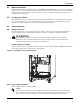
Liebert APM
Bypass Module
UHRF3S67X2
Positive
Neutral
Negative
Liebert
APM
DC Bus
Liebert
APM
Internal
Battery
CT
Output A
Output B
Output C
Output N
J9
J5
J4
J7
J1
12V
GND