
Installation manual

16 Chapter 2 Operation
Liebert APM Modular UPS User & Installation Manual
Chapter 2 Operation
This chapter introduces the basic knowledge of UPS operation, including the operating theory, operation mode,
battery management and battery protection of the UPS.
Warning: hazardous mains and battery voltage present behind covers
1. No user-serviceable parts are located behind covers that require a tool for their removal.
2. Only qualified service personnel are authorised to remove such covers.
2.1 Brief Introduction
The UPS provides continuous, high-quality AC power to your critical equipment, such as telecommunications and
data processing equipment. The UPS supplies power that is free of the disturbances and variations in voltage and
frequency common to mains power, which is subject to brownouts, blackouts, surges and sags.
The UPS uses the latest in high frequency, double-conversion pulse width modulation (PWM) technology and fully
digital control (DSP) technology to enhance its reliability and increase the ease of use.
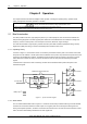
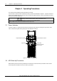
2.1.1 Operating Theory
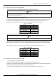
As shown in Figure 2-1, the AC mains source is converted by the rectifiers into DC power. The inverters convert that
DC power from the rectifiers or the DC power from the batteries into AC power, and provide the AC power for the load
through the output distribution modules. The batteries power the load through the inverters in the event of a power
failure. When the inverters are faulty or turned off, the mains source can also power the load through the static
bypass.
If maintenance or repair of the UPS is necessary, the load can be transferred without power interruption to the
maintenance bypass.
Maximally five power modules
Output distribution module 1
AC input 380V
Battery input
QF1
QF18
N
QF18
QF1
QF18
QF1
+
-
InverterRectifier
Static switch
Input switch
Q1
Maintenance bypass switch Q2
Output
switch Q3
InverterRectifier
Output distribution module 2
Output distribution module 3
Figure 2-1 System schematic diagram
2.1.2 Static Switch
The circuit block labeled static switch in Figure 2-1 contains an electronically controlled switching circuit that enables
the load to be connected to either the inverter output or to a bypass power source through the static bypass line.
During normal system operation, the load is connected to the inverters; but in the event of a UPS overload or inverter
failure, the load is automatically transferred to the static bypass line.