Precision Cooling For Business-Critical Continuity™ Liebert Deluxe System/3™ Operation and Maintenance Manual 50 and 60 Hz, 6-30 Ton DX Systems (DH/DE/VH/VE); 12-60 Ton CW Systems (FH/UH)
TABLE OF CONTENTS 1.0 INTRODUCTION . . . . . . . . . . . . . . . . . . . . . . . . . . . . . . . . . . . . . . . . . . . . . . . . . . . . . . . . . .1 1.1 System Description. . . . . . . . . . . . . . . . . . . . . . . . . . . . . . . . . . . . . . . . . . . . . . . . . . . . . . . . . . . 1 1.1.1 1.1.2 1.1.3 1.1.4 1.1.5 2.0 Compressorized Two-Step Systems . . . . . . . . . . . . . . . . . . . . . . . . . . . . . . . . . . . . . . . . . . . . . . . Compressorized Four-Step Systems . . . . . . . . . .
.4 Main Menu (AG)—View/Set Alarms . . . . . . . . . . . . . . . . . . . . . . . . . . . . . . . . . . . . . . . . . . . . 20 4.4.1 4.4.2 4.4.3 4.4.4 4.4.5 4.4.6 Active Alarms . . . . . . . . . . . . . . . . . . . . . . . . . . . . . . . . . . . . . . . . . . . . . . . . . . . . . . . . . . . . . . . Alarm History Log . . . . . . . . . . . . . . . . . . . . . . . . . . . . . . . . . . . . . . . . . . . . . . . . . . . . . . . . . . . Setup Alarms . . . . . . . . . . . . . . . . . . . . . . . . . . . . . .
.0 RESPONSE BY CONTROL TYPE—ADVANCED MICROPROCESSOR CONTROLS . . . . . . . . . . . 33 5.1 Temperature Control . . . . . . . . . . . . . . . . . . . . . . . . . . . . . . . . . . . . . . . . . . . . . . . . . . . . . . . . 33 5.1.1 5.1.2 5.1.3 5.1.4 5.2 35 35 35 36 36 Short Cycle Control . . . . . . . . . . . . . . . . . . . . . . . . . . . . . . . . . . . . . . . . . . . . . . . . . . . . . . . . . . 39 Sequential Load Activation Control . . . . . . . . . . . . . . . . . . . . . . . . . . . . . . . .
7.0 COMPONENT OPERATION AND MAINTENANCE, CHECKS AND ADJUSTMENTS . . . . . . . . . . . . 48 7.1 System Testing . . . . . . . . . . . . . . . . . . . . . . . . . . . . . . . . . . . . . . . . . . . . . . . . . . . . . . . . . . . . 48 7.1.1 7.1.2 Environmental Control Functions . . . . . . . . . . . . . . . . . . . . . . . . . . . . . . . . . . . . . . . . . . . . . . . 48 Electric Panel . . . . . . . . . . . . . . . . . . . . . . . . . . . . . . . . . . . . . . . . . . . . . . . . . . . . . . . . . . . .
FIGURES Figure 1 Figure 2 Figure 3 Figure 4 Figure 5 Figure 6 Figure 7 Figure 8 Figure 9 Figure 10 Figure 11 Figure 12 Advanced microprocessor control panel. . . . . . . . . . . . . . . . . . . . . . . . . . . . . . . . . . . . . . . . . . . . . . . 4 Advanced microprocessor (AM) control menu . . . . . . . . . . . . . . . . . . . . . . . . . . . . . . . . . . . . . . . . . . 5 Advanced microprocessor with graphics control panel . . . . . . . . . . . . . . . . . . . . . . . . . . . . . . . . . .
vi
Introduction 1.0 INTRODUCTION 1.1 System Description Liebert Deluxe environmental control systems are available in several configurations. Each configuration can operate with either Advanced Microprocessor Controls (AM), or Advanced Microprocessor Controls with Graphics (AG). A brief description of each, including operational differences, are listed below. Check model numbers to see what is supplied with your unit. 1.1.
Introduction 1.1.3 Chilled Water Systems These systems utilize a central chiller and control cooling by modulating a control valve in the chilled water line. Cooling Modulating output water valve Heating Three stages of electric reheat standard; steam/hot water optional Humidification Infrared standard, steam grid and steam generating optional Dehumidification Chilled water valve opens proportionally in response to room needs 1.1.
Initial Start-Up Procedure 2.0 INITIAL START-UP PROCEDURE Before beginning start-up, make certain that unit was installed according to the instructions in the Installation Manual. All exterior panels must be in place. Locate the Start-Up form supplied with your unit documents. Complete the form during your start-up and mail it to Liebert when start-up is completed. Contact your Liebert supplier if you have any questions or problems during your unit installation, start-up, or operation.
Advanced Microprocessor Controls Setup 3.0 ADVANCED MICROPROCESSOR CONTROLS SETUP The Advanced Microprocessor (AM) Control for your Liebert Deluxe unit features an easy to use menu driven LCD display. The menus, control features, and circuit board details are described in this section. For more control details refer to 5.0 - Response by Control Type—Advanced Microprocessor Controls, and for more alarm information refer to 6.0 - Alarm Descriptions and Solutions. 3.
Advanced Microprocessor Controls Setup Figure 2 Advanced microprocessor (AM) control menu Main Menu Normal Display 72° 50% Reheat Cooling Dehumidifying No Alarms Present Status/Alarm Data Setpoints/Setup Date and Time Status Display Status Alarm Data Active Alarms Operating Status Alarm History Log Run Hours Log Analog Sensors Active Operating Alarms Status No Alarms Present OR Alarm 01 of 01 High Head PR Use / to Scroll Alarm History Log Run Hours Log Alarm History Log Alarm 01 of 03 15-APR-09:20
Advanced Microprocessor Controls Setup 3.3 Main Menu (AM)—Status/Alarm Data Selecting STATUS/ALARM DATA from the Main Menu will display the following selections: ACTIVE ALARMS OPERATING STATUS ALARM HISTORY LOG RUN HOURS LOG ANALOG SENSORS 3.3.1 Active Alarms This screen, a submenu of Status/Alarm Data, displays any active alarm. The alarms are numbered, #1 being the most recent. If there are no active alarms, then “NO ALARMS PRESENT” will be displayed. 3.3.
Advanced Microprocessor Controls Setup 3.3.5 Analog Sensors The four (4) analog sensor inputs can be monitored from this submenu of Status/Alarm Data. The inputs are filtered and displayed along with the text label assigned during setup. See Analog Setup on page 12. 3.
Advanced Microprocessor Controls Setup Setup Operation The Setup Operation permits the review and/or adjustment of the unit configuration. The menu may include: Cold Start: This feature, also referred to as Positive Start or Winter Start Kit, allows for the lowpressure switch to be ignored for the programmed time during a cold start of the compressors, enabling the unit to run at low suction pressures. Entering a “0” for this time will bypass this feature.
Advanced Microprocessor Controls Setup Select Options The following table lists choices on the Select Options menu. These should match the options installed with your unit and should not need to change during normal operation.
Advanced Microprocessor Controls Setup Dehumidification with Normal or Delayed Reheat: Dehumidification with normal reheat allows for operating BOTH compressors and reheats simultaneously. It is very important that electrical service to the unit be sized and wired for this option if selected. ! CAUTION If the electrical service to the unit is not properly sized for this option, it could trip the building circuit breakers (or fuses) or, in extreme cases, damage the building wiring.
Advanced Microprocessor Controls Setup Table 5 Alarm default time delay Alarm Default Delay (seconds) Humidifier Problem 2 High Head Pressure 1 2 High Head Pressure 2 2 Change Filter 2 Loss of Air Flow 3 Custom Alarm #1 0 Custom Alarm #2 0 Custom Alarm #3 0 Custom Alarm #4 6 High Temperature 30 Low Temperature 30 High Humidity 30 Low Humidity 30 Low Suction Pressure 1, 2 0 Short Cycle 1, 2 0 Compressor #1 Overload 2 Compressor #2 Overload 2 Main Fan Overload 5 Loss of
Advanced Microprocessor Controls Setup Standard Alarm Messages • • • • • Water under floor Smoke detected Standby GC pump on Loss of water flow Standby unit on For more information concerning alarms, see 6.0 - Alarm Descriptions and Solutions. Humidity Control Method The user may select between relative (direct) and absolute (predictive) humidity control. If relative is selected, the RH control is taken directly from the RH sensor.
Advanced Microprocessor Controls Setup Set Status Display The Status Display can be set to show the return air temperature and humidity SENSOR READINGS or the temperature and humidity control SETPOINTS through this selection. When SETPOINTS is selected, the status display indicates so by displaying “SETPTS.” If SENSOR READINGS is selected, the Status Display will show the return air sensor readings.
Advanced Microprocessor Controls Setup Test Outputs When this feature is selected, the unit is effectively turned off. When stepping from one load to the next, the previous load, if on, is turned off automatically. The loads can also be toggled on/off by selecting “ENTER”. Once turned on, the output will remain on for 5 minutes unless toggled off or the Test Outputs function is exited by selecting “MENU/ESC”. (Compressor is limited to 15 seconds on to prevent damage.
Advanced Microprocessor Controls Setup 3.6 Main Menu (AM)—Status Display The Status Display shows the present room temperature, humidity, active status functions (cooling, heating, dehumidifying, humidifying), and active alarms. This is the data normally shown on the control screen. If no key is pressed for five minutes, the system automatically switches to the Status Display. The Status Display may also be selected from the Main Menu.
Advanced Microprocessor Controls Setup 3.8.2 Nonvolatile Memory All critical information is stored in nonvolatile memory. Setpoints, setup parameters, and component run hours are kept inside the microcontroller in EEPROM. Information retained for the alarm history is kept in non-volatile RAM. 3.8.3 DIP Switches Equipment options are selected and enabled using DIP switches 1 to 7. These are located at the upper left of the control board and are labeled SW1. Switch 1 is at the top.
Advanced Microprocessor Controls Setup 3.9.1 Monitor functions 1. 2. 3. 4. 5. 6. 3.9.2 Temperature/Humidity: Present readings Status: Cooling/Heating and Humidifying/Dehumidifying operating status in percent Present Alarms: Alarms presently active Alarm History: 10 most recent alarms (60 most recent alarms for AG) Run Time Log: Operating hours on major components Daily Log: High and Low Temperature & Humidity View/Change Functions 1.
Advanced Microprocessor with Graphics Control Setup 4.0 ADVANCED MICROPROCESSOR WITH GRAPHICS CONTROL SETUP The Advanced Microprocessor with Graphics (AG) Control for your Deluxe unit features an easy-touse, menu-driven LCD Graphics Display. The menus, control features, and circuit board details are described in this section. For more details on the control refer to 5.0 - Response by Control Type— Advanced Microprocessor Controls; for details on the alarms refer to 6.0 - Alarm Descriptions and Solutions.
Advanced Microprocessor with Graphics Control Setup Figure 4 Advanced microprocessor with graphics (AG) control menu 72°F Unit On 50% Reheat Dehumidifying Cooling Normal Display * * *Main Menu* * * View/Set Alarms Operating Status Operating Status Compressor Cooling % Heating % Glycool %** Chilled Water Valve %** Humidification % Active Alarms Alarm History Log Setup Alarms High Temperature Low Temperature High Humidity Low Humidity Low Suction Comp 1 Low Suction Comp 2 Short Cycle Comp 1 Short Cycle
Advanced Microprocessor with Graphics Control Setup 4.2 Display the Main Menu—AG Control Press the MENU/ESC key to display the Main Menu. The Menu selections include: • VIEW/SET ALARMS • OPERATING STATUS • VIEW/SET CONTROL SETPOINTS • SYSTEM SETUP • RUN DIAGNOSTICS • DATE AND TIME • PLOT GRAPHS • ANALOG/DIGITAL INPUTS • VIEW RUN HOURS LOG Pressing the MENU/ESC key while the Main Menu is displayed will return the screen to the Status Display. 4.
Advanced Microprocessor with Graphics Control Setup 4.4.3 Setup Alarms The list of alarms may be reviewed using the UP/DOWN keys. Any alarm may be selected to have its parameters modified by pressing the ENTER key. All alarms have a time delay and alarm type parameter. The high/low temperature and humidity alarms also have a programmable Trip Point. The Trip Point is the point at which the alarm is activated.
Advanced Microprocessor with Graphics Control Setup 4.4.4 Set Up Custom Alarms Selecting SETUP CUSTOM ALARMS will step to the following menu: • SETUP CUSTOM ALARM TEXT • CHANGE CUSTOM TEXT 1 • CHANGE CUSTOM TEXT 2 • CHANGE CUSTOM TEXT 3 • CHANGE CUSTOM TEXT 4 The custom alarm messages can be selected from a list of standard messages or you can write your own messages. The message selected for any custom alarm can be changed at any time by selecting SETUP CUSTOM ALARM TEXT.
Advanced Microprocessor with Graphics Control Setup 4.5 Main Menu (AG)—Operating Status The Operating Status is intended to provide the user with displayed information concerning what the control is calling for the system to do. NOTE There may be some time lapse before a specific component matches the displayed number. For example: The display indicates the chilled water valve is 68% open. On a new call for cooling, it takes several seconds for the valve to travel from full closed to 68% open.
Advanced Microprocessor with Graphics Control Setup 4.7.1 Setup Operation The SETUP OPERATION menu permits the review and/or adjustment of the unit configuration. This may include: Cold Start Delay This feature, also referred to as Positive Start or Winter Start Kit, allows for the low pressure switch to be ignored for the programmed time during a cold start of the compressor. Entering a “0” for this time will bypass this feature.
Advanced Microprocessor with Graphics Control Setup 4.7.2 Select Options The following table is a list of features that should match the options installed with your unit and should not need to change during normal operation.
Advanced Microprocessor with Graphics Control Setup 4.7.6 Select Humidity Sensing Mode This screen permits the user to select between RELATIVE (direct) and ABSOLUTE (predictive) humidity control. If relative is selected, the RH control is taken directly from the RH sensor. If absolute is selected, the RH control is automatically adjusted as the return air temperature deviates from the desired temperature setpoint. This results in predictive humidity control.
Advanced Microprocessor with Graphics Control Setup 4.8.1 Show Inputs With the unit on and the fan running, the input state for the following devices may be displayed: • • • • • • • • • • • • • • 4.8.
Advanced Microprocessor with Graphics Control Setup 4.8.4 DIP Switches The DIP switch settings can be reviewed from the display panel. Changing the DIP switches requires opening the front panel for access to the DIP switches on the microprocessor control board. NOTE Power MUST be cycled off, then on from the unit disconnect switch for the control system to update the DIP switch settings (except for switch 8).
Advanced Microprocessor with Graphics Control Setup Six different data types are recorded for graphing: temperature, humidity, and four user defined analog inputs. Each data type can be viewed over three different time scales and two different resolutions. The three time scales are 90 minutes, 8 hours, and 24 hours. The two resolutions are minimum and maximum. With minimum resolution selected, the full scale of the sensor is displayed.
Advanced Microprocessor with Graphics Control Setup 4.11.3 Read Digital Inputs The four custom alarm inputs can be defined to be digital inputs. Digital inputs are used to sense customer devices for status display purposes only and will not activate the audible alarm. 4.11.4 Set Up Digital Inputs A digital input is enabled by defining one of the four custom alarms to be STATUS ONLY type in the alarm setup screen.
Advanced Microprocessor with Graphics Control Setup 4.13.3 Compressor Sequencing Control The lead compressor is the first one to be turned on when compressor operation is required. The lag compressor is turned on second if both compressors are required. The control monitors the operating time of both compressors and will automatically switch lead/lag compressor operation to maintain less than eight hours difference between the running times of two compressors.
Advanced Microprocessor with Graphics Control Setup 4.14.4 Control Outputs Active control outputs are indicated with LEDs on the lower section of the control board. Each LED is lit if the control output is active (on). Use these LEDs to assist in troubleshooting the system. Table 12 Control output LEDs 4.
Response by Control Type—Advanced Microprocessor Controls 5.0 RESPONSE BY CONTROL TYPE—ADVANCED MICROPROCESSOR CONTROLS This section describes how your Advanced Microprocessor Controls respond depending on the algorithm/control type selected in setting up the controls. 5.1 Temperature Control 5.1.
Response by Control Type—Advanced Microprocessor Controls 5.1.3 Cooling Operation Two-Step Cooling, Compressorized Direct Expansion (DX) Systems The first stage of cooling activates when the temperature control calculates a requirement for cooling of 50%. The first stage of cooling is deactivated when the cooling requirement drops below 25%. The second stage of cooling is activated when the requirement for cooling rises to 100% and deactivated when the requirement falls below 75%.
Response by Control Type—Advanced Microprocessor Controls Hot Water/Steam Heat The valve begins to open when the requirement for heating is 33% and is proportionally adjusted until the valve is full open at 100% heat requirement. 5.2 Humidity Control 5.2.1 Dehumidification/Humidification Required, in Percent (%) The humidity control program for the Advanced Microprocessor is based on a calculated % requirement for dehumidification/ humidification.
Response by Control Type—Advanced Microprocessor Controls Dual Cooling Source Dehumidification When dual cooling is available, the humidity control will calculate a total dehumidification requirement of 200% rather than 100%. The cooling valve opens proportionally as the requirement for dehumidification rises from 0 to 100%. If more than 100% dehumidification is required, then the compressors are activated at 150% and 200% respectively.
Response by Control Type—Advanced Microprocessor Controls Suggested System Tuning Procedure 1. Initially adjust the integral and derivative settings to 0%/degree-min and 0%/degree/min. 2. Starting with 20% /degree, adjust the proportional setting in small increments (10% steps) until the control sustains a constant hunting action (the temperature swings are approximately the same amplitude from one peak to the next). 3.
Response by Control Type—Advanced Microprocessor Controls Intelligent Control The Intelligent Control operates from a set of general rules that define how the control output should be adjusted for different system conditions. The rules are designed to duplicate the actions that an experienced human operator would take if manually controlling the system.
Response by Control Type—Advanced Microprocessor Controls 5.3 Load Control Features 5.3.1 Short Cycle Control The control system monitors both compressors and prevents each from turning on within a 3 minute period of being turned off. If this (on, off, on) occurs too often, ten (10) times in a one hour period, a Short Cycle alarm could occur. 5.3.2 Sequential Load Activation Control The control allows only one load output to be energized at a time on a restoration of power or microcontroller reset.
Response by Control Type—Advanced Microprocessor Controls 5.4 Analog Sensors 5.4.1 Connecting the Analog Sensors The sensor inputs are factory-set to accept a 4 - 20 mA signal. The inputs can be changed by removing the appropriate jumpers on the control circuit board. See Table 13, Figure 5 and Figure 6. The user supplied analog sensors MUST have their own power supply.
Response by Control Type—Advanced Microprocessor Controls 5.4.2 Water Detection Display The water detection display is designed to graphically display the location of water under a raised floor when connected to an LT750 water detection system. The graphical floor plan screen shows a 30 x 16 grid. Each square represents one standard floor tile (approximately 2 ft. x 2ft.).
Response by Control Type—Advanced Microprocessor Controls Calibration Calibration should not be required for most installations. The accuracy of this display is approximately 1%. The display is calibrated by the slope and intercept values of Analog Input #1.
Response by Control Type—Advanced Microprocessor Controls 5.5.2 View/Change Functions: 1. Setpoints Temperature Setpoint Temperature Sensitivity Humidity Setpoint Humidity Sensitivity High Temperature Alarm Low Temperature Alarm High Humidity Alarm Low Humidity Alarm Cold Start Delay Humidifier Flush Rate Chilled Water Flush Rate 2. Control Type: proportional, PID, intelligent 3. PID Parameters: Proportional, Derivative and Integral Gains 4. On/Off Status 5. Time: View Only 6.
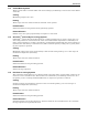
Alarm Descriptions and Solutions 6.0 ALARM DESCRIPTIONS AND SOLUTIONS The Advanced Microprocessor (AM) and the Advanced Microprocessor with Graphics (AG) Control systems will audibly and visually annunciate all Enabled alarms, including the four (4) custom alarms. With the AM & AG Controls, the customer alarms can be from the optional alarm list and/or can have their own fully custom text. Two (2) alarms may be selected as custom for AM and four (4) can be custom for AG.
Alarm Descriptions and Solutions 6.1.3 Custom Alarms (Only With Advanced Controls) Custom alarm messages are programmed at the LCD display. The alarms may be specified by the customer at the time of order. Additional devices and wiring may be required at the factory or by others. The message displayed may be included in this alphabetical list of alarms, or it may be customized text (for up to 2 alarms).
Alarm Descriptions and Solutions 6.1.10 Loss of Air Flow A differential air pressure switch is used to indicate loss of air flow in Deluxe units. Check for blockage of unit air outlet or inlet. Check blower motor fuses and overload reset. Check for broken belts. Make sure blower wheels are tight to shaft. Run diagnostics to see if the fan contactor is working properly. 6.1.
Alarm Descriptions and Solutions 6.2 Optional/Custom Alarms 6.2.1 Loss of Water Flow No water flow is detected in the chilled water or condenser water supply line. An optional flow switch is required for this alarm. Check for service valves closed, pumps not working, etc. 6.2.2 Smoke Detected Smoke is detected in the return air by an optional Liebert Smoke Detector. Check for source of smoke or fire, and follow appropriate emergency procedures. 6.2.
Component Operation and Maintenance, Checks and Adjustments 7.0 COMPONENT OPERATION AND MAINTENANCE, CHECKS AND ADJUSTMENTS 7.1 System Testing ! 7.1.1 WARNING Potentially lethal voltages exist within this equipment during operation. Observe all cautions and warnings on unit and in this manual. Failure to do so could result in serious injury or death. Only qualified service and maintenance personnel should work with this equipment.
Component Operation and Maintenance, Checks and Adjustments 7.1.2 Electric Panel The electric panel should be inspected for any loose electrical connections. ! WARNING Be sure that power to the unit is shut down before attempting to tighten any fittings or connections. Control Transformer and Fuses The control system is divided into four (4) separate circuits. Fuses located on the transformer/fuse board individually protect the control voltage circuits.
Component Operation and Maintenance, Checks and Adjustments 7.2 Filters Filters are usually the most neglected item in an environmental control system. To maintain efficient operation, they should be checked monthly and changed as required. Because replacement intervals vary with environmental condition and filter type, each unit is equipped with a filter clog switch. This warns of restricted airflow through the filter compartment by activating the Change Filter alarm.
Component Operation and Maintenance, Checks and Adjustments 7.3.3 Electronic Variable Speed Drive (Inverter) On large Deluxe chilled water models an optional variable speed drive inverter is available. This packaged unit is factory set and should not require field adjustments. The variable speed drive saves power by reducing blower speed to match unit load. If you suspect a problem with the inverter, first make sure that the INTELLIGENT CONTROL method is selected at the microprocessor.
Component Operation and Maintenance, Checks and Adjustments 7.4.2 Suction Pressure Suction pressure will vary with load conditions. The low pressure switch will shut the compressor down if suction pressure falls below the cut-out setting. On the other hand, high suction pressure reduces the ability of the refrigerant to cool compressor components and can result in compressor damage.
Component Operation and Maintenance, Checks and Adjustments Adjustment To adjust the superheat setting, proceed as follows: 1. Remove the valve cap at the bottom of the valve. 2. Turn the adjusting stem counterclockwise to lower the superheat. 3. Turn the adjusting stem clockwise to increase the superheat. NOTE Make no more than one turn of the stem at a time. As long as thirty minutes may be required for the new balance to take place. 7.4.
Component Operation and Maintenance, Checks and Adjustments 7.4.7 Air Cooled Condenser Restricted airflow through the condenser coil will reduce the operating efficiency of the unit and can result in high compressor head pressure and loss of cooling. Clean the condenser coil of all debris that will inhibit air flow. This can be done with compressed air or commercial coil cleaner. Check for bent or damaged coil fins and repair as necessary.
Component Operation and Maintenance, Checks and Adjustments 7.4.8 Water/Glycol Cooled Condensers Shell and Tube Condensers Each water or glycol cooled module has a shell and tube condenser which consists of a shell, removable heads, gaskets and cleanable copper tubes. It may be necessary to clean the copper tubing periodically to remove any scale or lime that should collect (periods between cleanings will vary with local water conditions).
Component Operation and Maintenance, Checks and Adjustments 7.4.9 Compressor Replacement ! CAUTION Avoid touching or contacting the gas and oils with exposed skin. Severe burns will result. Use long rubber gloves in handling contaminated parts. Infrequently, a fault in the motor insulation may result in a motor burn. However, in a properly installed system, burnouts rarely occur.
Component Operation and Maintenance, Checks and Adjustments Compressor Replacement Procedure Replacement compressors are available from your Liebert supplier. They will be shipped in a reusable crate to the job site as required by the service contractor. Upon shipping a replacement compressor, the service contractor will be billed in full for the compressor until the replacement has been returned to the factory. The compressor should be returned in the same container used for shipping to the job.
Component Operation and Maintenance, Checks and Adjustments Changing Humidifier Lamps 1. 2. 3. 4. Open disconnect switch. Open middle front panel. Remove screws securing line voltage compartment cover, then remove the cover. In line voltage compartment, disconnect one end of the purple jumpers, then locate the burned-out bulb with a continuity meter. 5. Remove humidifier pan. 6. Remove lamp brackets (3) under lamps. ! Figure 9 CAUTION Do not touch the quartz lamps with your bare hands.
Component Operation and Maintenance, Checks and Adjustments 7.5.2 Steam Generating Humidifier The humidifier drains and refills to maintain a current setpoint and alert the operator when the humidifier canister needs to be replaced. The humidifier is located in the lower section of upflow units, and in the middle section of downflow units. Figure 10 Steam generating humidifier Operation 1.
Component Operation and Maintenance, Checks and Adjustments Controls The humidifier RUN/DRAIN switch is located in the unit low voltage compartment for most Deluxe models (in the humidifier assembly for models FH599, 600, 739, 740C). This switch should be in the RUN position when the humidifier is in normal operation; it should be in the DRAIN position when a manual drain for service is required. The electronic control board for the humidifier is located in the same area as the humidifier RUN/DRAIN switch.
Component Operation and Maintenance, Checks and Adjustments 11. The canister is now ready to be removed. On the downflow chilled water units: Slide the humidifier cabinet bottom straight out toward you and drop the canister through the bottom of the cabinet. On all other units: Pull the canister straight out of the cabinet toward you. 12. Replace the canister with the part indicated in the following table.
Component Operation and Maintenance, Checks and Adjustments Circuit Board Adjustments ! WARNING Circuit board adjustment should be performed by qualified personnel only. Hazardous voltages are present in the equipment throughout the procedure. Use extreme caution. If desired, power may be disconnected prior to the procedure. NOTE Numbers and percentages within parentheses ( ) in the following paragraphs refer to circuit board settings for downflow models FH599C, 600C, 739C and 740C.
Component Operation and Maintenance, Checks and Adjustments Figure 12 Steam generating humidifier control board Table 20 DIP switch settings for steam generating humidifier Rated Values Unit Rated Voltage Capacity SW1 SW2 SW3 SW4 Voltage AMP Set Pt 200/208 11 Off On Off On 208 12.6 200/208 22 On Off On On 208 23.8 230 11 Off Off Off On 240 10.5 230 22 Off Off On On 240 20.3 380/400/415 11 On On Off Off 400 6.3 380/400/415 22 Off On On On 400 12.
Troubleshooting 8.0 TROUBLESHOOTING Use this section in troubleshooting your unit. Also refer to 6.0 - Alarm Descriptions and Solutions. Suggestions are grouped by product function for convenience. Table 21 ! WARNING ! CAUTION Only qualified personnel should perform service on these units. Lethal voltage is present in some circuits. Use caution when troubleshooting with power on. Disconnect and lock out power before replacing components.
Troubleshooting Table 23 Compressor and refrigeration system troubleshooting Symptom Compressor will not start Possible Cause Check or Remedy Power off Check main switch, fuses or CBs and wiring Current overload open Reset manually Loose electrical connections Tighten connections Compressor motor burned out Check and replace compressor if defective. No call for cooling Check monitor status. Solenoid valve not energizing Hold screwdriver over solenoid and check for magnetic field.
Troubleshooting Table 23 Compressor and refrigeration system troubleshooting (continued) Symptom Refrigerant flooding Blown valve plate or cylinder head in comp. Low compressor capacity or inability to pull down system Compressor noisy Pipe rattle Compressor running hot Compressor cycles intermittently Possible Cause Check or Remedy Defective or improperly set expansion valve Increase superheat or replace valve Evaporator fan motor or belt Correct problem or replace fan motor and/or belts.
Troubleshooting Table 23 Compressor and refrigeration system troubleshooting (continued) Symptom Compressor continually cycles Compressor motor protectors tripping or cycling Compressor cycles on locked rotor Motor burnout Table 24 Check or Remedy Faulty low pressure switch Repair or replace. Dirt or restriction in tubing to pressure stat Check and clean tubing. Defective liquid line solenoid valve Check valve and solenoid operator; replace if necessary.
Troubleshooting Table 26 Humidifier—steam generator troubleshooting Symptom False canister full indication Main 24 VAC fuse or circuit breaker trips Possible Cause Check or Remedy Check drain valve to ensure that it drains freely. Check and replace if defective. Foaming Check water supply. If commercially softened, reconnect to raw water supply. If connected to hot water reconnect to cold water. Shorts or loose connections Check the wiring connections of the 24 VAC circuit.
Troubleshooting Table 26 Humidifier—steam generator troubleshooting (continued) Symptom Excessive arcing in the canister On cold start-up, canister fills, high water alarm activates and humidifier fails to reach full amperage after 24 hours Table 27 Possible Cause Check or Remedy Drain valve clogged or defective Verify that drain valve operates freely when activated. Clean valve and replace coil or valve if defective.
Maintenance Inspection Checklist—Monthly 9.0 MAINTENANCE INSPECTION CHECKLIST—MONTHLY Date: Prepared by: Model #: Serial #: Filters Refrigeration Cycle/Section 1. Unrestricted air flow 1. Check suction pressure 2. Check filter switch 2. Check refrigerant lines 3. Wipe section clean 3. Check head pressure 4. Check for moisture (sight glass) Blower Section 1. Impellers free of debris 5. Check discharge pressure 2. Bearings free 6. Check hot gas bypass valve 3.
Maintenance Inspection Checklist—Semiannual 10.0 MAINTENANCE INSPECTION CHECKLIST—SEMIANNUAL Date: Prepared by: Model #: Serial #: Filters Refrigeration Cycle/Section 1. Unrestricted air flow 1. Check suction pressure 2. Check filter switch 2. Check refrigerant lines 3. Wipe section clean 3. Check head pressure 4. Check for moisture (sight glass) Blower Section 1. Impellers free of debris 5. Check refrigerant level 2. Bearings free 6. Check discharge pressure 3.
Ensuring The High Availability 0f Mission-Critical Data And Applications. Emerson Network Power, the global leader in enabling business-critical continuity, ensures network resiliency and adaptability through a family of technologies—including Liebert power and cooling technologies—that protect and support business-critical systems. Liebert solutions employ an adaptive architecture that responds to changes in criticality, density and capacity.