
User manual


Piping Schematics
101 Liebert
®
DS
™
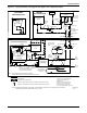
Figure 73 Piping schematic—GLYCOOL with scroll compressor models
3-Way
Chilled Glycol
Valve
3-Way
Chilled Glycol
Valve
NOTE: Schematic representation shown. This schematic does not imply or define elevations and
component location, unless specifically noted.
Service
Valve
* Components are not supplied by
Liebert but are recommended for
proper circuit operation and
maintenance
** Field installed at highest point in
system on return line to pumps
*** Locate at tops of all risers and
any intermediate system high points
External
Equalizer
Sensing Bulb
NOTE: Two refrigeration circuits provided.
Single refrigeration circuit shown for clarity.
FIELD PIPING
FACTORY PIPING
EVAPORATOR
COIL
Expansion
Valve
COMPRESSOR
LIQUID
SUCTION
Sight
Glass
Solenoid
Valve
Filter Dryer
DPN000898
REV 3
Paradenser
Condenser
To Second
Refrigeration
Circuit
Hose
Bib*
Hose
Bib*
Shutoff Valve*
Shutoff Valve*
Shutoff Valve*
Shutoff Valve*
Flow-Regulating
Valve*
Flow Switch
Supplied with Dual
Pump Systems
Pressure Port*
Gate Valves*
Check Valves*
(on Dual Pump
Systems only)
GLYCOL PUMPS
EXPANSION
TANK**
Hose
Bib*
ECON-O-COIL
LIEBERT
HEAT REJECTION
DRYCOOLER
(Glycol)
Aquastat
Sensing
Bulbs
Pressure
Port*
3-Way
Regulating
Valve
Sensor
Air V
ents
(typical)***
LIEBERT DS UNIT
(and associated piping)
RETURN
RETURN
SUPPLY
SUPPLY
Relief valve(s) supplied
with 50 Hz EU CE units rated
maximum 480 PSIG (33 Bar).
Thermistor
DISCHARGE
SERVICE / SCHRADER (ACCESS) CONNECTION WITH VALVE CORE
SERVICE / SCHRADER (ACCESS) CONNECTION NO VALVE CORE
Check
Valve
Optional Dual Pump System shown
®
For systems with drycoolers,
refer to 13.14.3 - Drycooler Settings.