
User manual


Piping Schematics
107 Liebert
®
DS
™
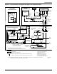
Figure 79 Primary connection locations—downflow water/glycol/GLYCOOL 28-42kW (8-12 ton), all
compressor models
Point Description
X
in. (mm)
Y
in. (mm)
Connection Size / Opening
in. (mm)
W Water/Glycol/GLYCOOL Access 79-15/16 (2030) 9-1/16 (230) 3-1/2 x 8 (89 x 203)
WS Water/Glycol/GLYCOOL Supply 82-15/16 (2107) 10-15/16 (278) 1-5/8" Cu Sweat
WR Water/Glycol/GLYCOOL Return 82-15/16 (2107) 14-1/16 (357) 1-5/8" Cu Sweat
CD
Condensate Drain
(infrared humidifier or no humidifier) *
46 (1168) 29-1/2 (749) 3/4" FPT
Condensate Drain
(steam generating humidifier) *
46 (1168) 29-1/2 (749) 1-1/4" FPT
W/ Optional Pump 46 (1168) 29-1/2 (749) 1/2" Cu Sweat
HUM Humidifier Supply Line 53-1/2 (1359) 29 (737) 1/4" Cu Sweat
ECS Econ-O-Coil Supply 54-7/8 (1394) 22-9/16 (573) 1-5/8" Cu Sweat
ECR Econ-O-Coil Return 49-13/16 (1265) 28-1/2 (724) 1-5/8" Cu Sweat
E1 Electrical Conn. (High Volt) 55-1/2 (1410) 31-1/4 (794) 2-1/2"
E2 Electrical Conn. (High Volt) 52-7/16 (1332) 31-1/4 (794) 2-1/2"
LV1 Electrical Conn. (Low Volt) 2-1/4 (57) 27 (686) 7/8"
LV2 Electrical Conn. (Low Volt) 2-1/4 (57) 29 (737) 7/8"
LV3 Electrical Conn. (Low Volt) 2-1/4 (57) 31 (787) 7/8"
B Blower Outlet 21-15/16 (557) 18-1/16 (459) 18-3/4 x 16-1/16 (476 x 408)
* Field pitch condensate drain line a minimum of 1/8" (3.2 mm) per foot (305 mm). All units contain a factory-installed condensate trap. Do
not trap external to the unit. Drain line may contain boiling water. Select appropriate drain system materials. The drain line must comply
with all local codes.
Source: DPN000900, Rev. 3
WS
WR
W
ECS
ECR
E1
E2
HUM
CD
B
O
X
Y
FRONT VIEW
LV1
NOTE: Drawing not to scale.
Tolerance on
all piping dimensions
is ± 1/2" (13mm).
8"
(203mm)
3-1/2"
(89mm)
BLOWER
OUTLET
ALL DIMENSIONS FROM
REAR CORNER OF UNIT
INCLUDING PANELS
16-1/16"
(408mm)
35"
(889mm)
86"
(2184mm)
LV2
LV3
SECTION A-A
FRONT OF UNIT
AA
DPN000900
Rev. 3