
User manual


Liebert DS Components and Nomenclature
Liebert
®
DS
™
4
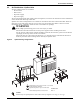
Figure 2 Upflow model component locations
1
2
4
5
6
7
8
9
10
11
12
13
14
15
16
17
18
1. Liebert iCom Control Display
2. Electric Box
3. Filters - not shown for clarity
4. Evaporator Coil
5. Motor
6. Blower
7. Fan Pulley
8. Motor Sheave and Belts
9. Compressor Section
10. Infrared Humidifier (optional)
11. Disconnect (optional)
12. Condensate Pump (optional)
13. Smoke Sensor (optional)
14. Condenser Cleanout Plugs (fluid-cooled units only)
15. Condenser Drain Plugs ( fluid-cooled units only)
16. Econ-O-Coil Valve (GLYCOOL/Dual Cooling)
17. Variable Frequency Drive (optional on
digital scroll units only)
18. EC Fans (optional)
DPN001222
Rev. 1
Not all combinations of options available on all units. Consult factory.