
User manual


Maintenance
135 Liebert
®
DS
™
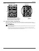
13.2.1 Upflow Motor Access
1. Remove the lateral support (sheet metal channel) under electric box by removing two screws at
each end.
2. Removed the hinged deadfront panel (30-ton units have open access to the motor).
3. Remove two screws on the right side of the low-voltage electric box that secure the low volt
electric box to the sheet metal shoulder.
4. Swing open low-voltage electric box to gain access to the motor.
Figure 99 Upflow motor access
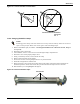
13.2.2 Belt Removal
1. Disconnect power to unit.
Do not pry the belts off sheave or pulley.
2. Refer to instruction labels on unit near motor base.
3. Turn adjustment nut (see Figure 100) counterclockwise (left) to loosen belts and bring motor
base internal spring out of compression.
4. Remove belts.
13.2.3 Belt Installation and Tensioning
1. Select the appropriate replacement of belts (matched set) and position on drive package.
To maximize performance and reliability of Liebert DS equipment, use only Liebert belts. Contact
your local Emerson representative for replacement belts.
2. Ensure pulley grooves are properly aligned. If adjustment is required, loosen (do not remove) four
nuts in adjustment slots (see Figure 100) holding motor base to unit frame and slide motor base
assembly into alignment.
3. Tension belts by turning adjustment nut clockwise (right) until motor base carriage stops
moving downward.
4. Ensure minimum 1/2" (12.7mm) clearance exists from motor base carriage to base front flange
(see Figure 100). If the clearance is less than 1/2" (12.7mm), select shorter belts.
5. Mark the adjustment nut and rotate clockwise (right) five additional full turns. This sets internal
spring for proper belt tension, no readjustments necessary.
DPN001221
Rev. 0
Hinge
Deadfront
Screws
Screws
Lateral Support
Low Voltage
Electric Box