
User manual


Maintenance
145 Liebert
®
DS
™
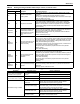
Figure 107 Circuit board diagram
13.6 Condensate Drain and Condensate Pump Systems
13.6.1 Condensate Drain
Check and clear obstructions in tubing during routine maintenance.
13.6.2 Condensate Pump
• Disconnect power to unit using disconnect switch.
• Check and clear obstructions in gravity lines leading to condensate pump.
• Remove sump and clean with a stiff nylon brush and flush with water.
• Inspect and clear clogs in discharge check valve and float mechanism.
• Reassemble and check for leaks.
!
WARNING
Risk of electric shock. Can cause injury or death.
The Liebert iCOM microprocessor does not isolate power from the unit, even in the “Unit Off”
mode. Some internal components require and receive power even during the “unit off” mode of
the Liebert iCOM control.
Disconnect local and remote power supplies before working within.
J18
J19
J17
J20
J16
J21
J15
J22
J14
J13
J12
J1 1
P1 1
1
1
P12
J1
J2
J3
J4
J5
J6
J7
Current
Transformer
J23
J10
J8
J9
J25
J26
J24
200V/208V: J6, J9, J15*, J17*, J19*, J10*, J23*, P11 pin (2-3)*
230V: J5, J9, J15*, J17*, J19*, J10*, J23*, P11 pin (2-3)*
380V/415V: J3, J8, J15*, J17*, J19*, J10*, J23*, P11 pin (2-3)*
460V: J2, J8, J15*, J17*, J19*, J10*, J23*, P11 pin (2-3)*
575V: J1, J8, J15*, J17*, J19*, J10*, J23*, P11 pin (2-3)*
To configure the PCB to the proper voltage,
the jumpers should be set as follows:
PCB is configured for: MES-L
(* = Factory setting; do not adjust)
Capacity adjust
(Default at 100%)
Sealed,
do not adjust
Green
LED
Yel lo w
LED
CURRENT TRANSFORMER
For MES-L 10, loop current-sensing wire twice
through current-sensing coil.
For MES-L 20, loop current-sensing wire once
through current-sensing coil.
J6: 200-208
J5: 230V
J3: 380-415
J2: 460V
J1: 575V
Mains Voltage
Select Jumpers
HW Sensor Jumpers
J9: Low Voltage 200-240V
J8: High Voltage 380-600V