
User manual


Maintenance
149 Liebert
®
DS
™
13.13.1 Cleaning Instructions
Refer to Figure 1 - Downflow model component locations.
1. Disconnect power to unit.
2. Close field-installed isolation valves to isolate this unit’s condenser system from facility water or
glycol circuit.
3. Remove access panel from front of compressor section.
4. Locate the 1/2" NPT drain plugs located at lower front of compressor section and provide means to
collect fluid drained from system
5. Remove the 1/2" drain plugs using two wrenches to prevent damage to drain lines.
6. Locate and remove the 3" diameter clean out plugs on top of shell assemblies (use
Craftsman
™
1-3/16" drag link socket, Sears item # 00944514000 or similar).
7. Brush and flush each of the nominal 5/8" inner diameter, rifled copper tubes. Recommend using
John R. Robinson, Inc. or similar:
• Motorized Tube Cleaner, Model JR3800-1200
• Nylon brush 9/16" diameter, Model JRRB211N-916
• Flexible shaft, Model JRRFS702-25
8. Reinstall 1/2" drain plugs 6 to 7 turns using Loctite 567 PST Thread Sealant as instructed by the
manufacturer.
9. Wipe clean the machine threads and sealing surfaces of 3" diameter clean out plugs.
10. Remove and install new O-rings (Liebert part number 180750P1) on the 3" diameter clean out
plugs. (Do not use thread sealant).
11. Hand tighten 3" diameter clean out plugs and torque using drag link socket to 25 ft-lb.
12. Leak check fluid system (refer to Leak Checking of Unit and Field Piping on page 87).
13. Bleed system using Schrader ports near the top of the Paradenser.
14. Ensure that condensing fluid isolation valves are fully open.
15. Unit is ready to be put on-line.
13.14 Water/Glycol Control Valves
13.14.1Regulating Valves – Semi Hermetic and Standard Scroll Compressors
The water regulating valves automatically regulate the amount of fluid necessary to remove the heat
from the refrigeration system, permitting more water to flow when load conditions are high and less
fluid to flow when load conditions are low. The valve consists of a brass body, balance spring, valve
seat, valve disc holders, capillary tube to discharge pressure, and adjusting screw.
Adjustment—Johnson Controls Valves
The valves may be adjusted with a standard refrigeration service valve wrench or screwdriver.
To lower the head pressure setting, turn the square adjusting screw clockwise until the high pressure
gauge indicates the desired setting. To raise the head pressure setting, turn the adjusting screw
counterclockwise until the desired setting is obtained. Consult the factory if your unit is equipped
with valves from other manufacturers.
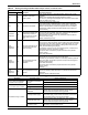
Table 63 Recommended refrigerant pressures
System Design
PSIG (kPa)
Water-Cooled
65 to 75°F water (18 to 24°C) 210 (1450)
85°F water (29°C) 225 (1550)
Glycol-Cooled 295 (2035)
Maximum 330 (2275)
High Pressure Cut-out 400 (2859)