
User manual


Disassembling the Liebert DS for Transport
51 Liebert
®
DS
™
7.2 Disassembly—Downflow Units
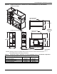
For detailed views of downflow units, see Figures 43 through 51.
1. Remove the unit from its shipping skid before beginning (refer to 5.2 - Unpacking the Unit).
2. Remove all panels except the top front accent.
3. Remove all filters. This allows access to the screws for metal plate blocking off the top coil and
removal of the filter plate.
4. All wires are hot-stamped and all circuit board connectors are lettered to ease connection. Some
cable ties must be cut and replaced. Refer to the unit’s wiring schematic on the unit’s deadfront
panel for details.
NOTICE
Do not lay the compressor section on its side. It must remain upright. The coil section also
must remain upright.
5. Label the three quick-connect plugs from the compressor compartment and disconnect them.
6. Disconnect the compressor wire harness, including the crankcase heater wires, if present, from
the contactor in the electric box.
7. Pull the conduit and wires into the compressor compartment.
8. Disconnect the fan motor wire harness from the bottom of the contactor in the electric box.
9. Pull the conduit and wires into the bottom section of the Liebert DS.
10. Reheat—Optional Component
a. Disconnect the reheat wire harness from the bottom of the contactor in the electric box.
b. Unplug the low-voltage quick connect for the reheat safety wires.
c. Pull the conduit and wires into the unit’s blower and coil assembly section.
11. Humidifier—Optional Component
a. Disconnect the humidifier wire harness from the bottom of the contactor in the electric box.
b. For infrared humidifiers: Remove the quick-connect plugs from the following low-voltage
connections: 35-5 and 35-6 (safety under pan), 35-3 and 35-4 (humidifier make-up valve), and
8-5 and 8-7 (high water alarm).
For steam generating humidifiers: Remove the quick-connect plugs from the following
low-voltage connections: 35-1, H-24H and H-24G, and 35-7 and HAR-24H.
c. Disconnect 35-3 and 35-4 from the control board.
d. Pull the conduit and wires into the unit’s blower and coil assembly section.
12. Condensate Pump—Optional Component
a. Disconnect the condensate pump’s high-voltage wiring harness.
b. Remove the low-volt wires from terminal strips #24 and #55.
c. Pull the conduit and wires into the unit’s blower and coil assembly section.
13. GLYCOOL/Dual-Cool—Optional Component
a. On units with an actuator, unplug the valve actuator harness at the actuator and pull the
wire harness into the electric box.
b. Disconnect the glycol sensor from the control board and pull it into the unit’s blower and coil
assembly section.
14. Disconnect the air sail switch wires and pull them into the electric box.
15. Smoke Detector—Optional Component
a. Remove the smoke detector cover.
b. Remove the plug connector from the smoke detector and pull it into electric box.
c. Remove the wires from terminal strips #91, 92, 93 and route them into the smoke detector
box.
d. Remove the sensing tube from top of the smoke detector.
The wand and tube will remain attached to filter and electric box assembly.
16. Close the electric box cover and the accent panel.
17. Remove the pull bar that supports the accent panel from the left end of unit, otherwise it will fall
out when the compressor section is removed.