
User manual


Disassembling the Liebert DS for Transport
53 Liebert
®
DS
™
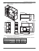
7.2.2 Remove the Filter and Electric Box Assembly
1. Using a stepladder to reach the top of the Liebert DS, remove the filter support plate; it is
attached to the filter and electric box assembly with two screws, one on each end.
2. Remove tags from the Schrader fittings on top of the coil headers. Retain the tags for replacement
during reassembly.
3. Remove 16 screws, (8) on each side, from the evaporator top cover plate to coil assembly. Coil top
blocker will remain with top section for rigidity.
4. Remove coil access plates from the left side of the Liebert DS.
5. Remove the four thread-cutting bolts securing the filter and electric box assembly to the blower
and coil assembly. There are two on the left and two on the right.
6. Separate the unit sections with caution.
NOTICE
Risk of improper handling.
• The filter and electric box section should be moved forward and set on the floor.
• Make sure to lift the coil plate over the Schrader fittings on the headers. Emerson
recommends using four people to remove this section. Special care is required when moving
this section because the legs are not designed to withstand strong shocks.
• The blower and coil assembly must remain upright. The coil is not secured to the blower
and coil assembly.
• Secure the coil to the bottom section with straps or a similar method before moving the
section.
7. Move each section of the Liebert DS to the installation location.
7.3 Reassembly—Downflow Units
1. Replace the top section.
Make sure to clear the Schrader valves on the coil header.
2. Reconnect the filter and electric box assembly to the blower and coil assembly using thread-
cutting bolts.
Torque the bolts to 225 in-lb. (25Nm)
3. Reattach the evaporator top cover plate; there are eight screws on each side.
4. Reattach the filter support plate to the filter and electric box assembly; there is one screw on each
side.
5. Reattach the tags to the Schrader fittings on top of the coil headers.
6. Replace the compressor section.
Insert all compressor thread-cutting bolts before tightening any of the bolts.
7. Reinstall the pull bar to support the accent panel.
8. Reattach the low-voltage plugs in the compressor section.
9. Reconnect the wiring for the compressor, fan motor, reheat, humidifier, condensate pump, smoke
detector and air sail switch.
10. Reattach the sensing tube to the top of the smoke detector.
11. On GLYCOOL and dual-cool units, reattach the plug connection at the actuator and reroute the
sensor wire back through the electric box and onto the control board.