
User manual


Electrical Connections
Liebert
®
DS
™
78
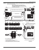
Figure 62 Electrical field connections—Upflow and downflow models, dual fused disconnect switches
75
76
94
95
96 97 91
11
12
92
93
80
81
72
37C
38C
37B
38B
37 38 24
70
71
230
50
51
55 56
88
83
82 89
84
59
58 85
PRIMARY
SECONDARY
Alternate
Location
Alternate
Location
73
17 18
9
16
19
20
10
8
21
23
24
22
7
3
1
13
6
15
14
4
A
B
CD
A
B
CD
P64
P67
6
60 Hz
3
15
2
12
SH49-1
49-3
11
E
E
OVERCURRENT PROTECTION DEVICES
CONTACTORS, RELAYS and
OVERLOAD PROTECTORS
Typical orientation of components shown.
Component location varies by option and unit size
DOWNFLOW
UPFLOW
DOWNFLOW LOW-VOLTAGE SECTION
Liebert
IntelliSlot
Housing
Item 12 Installation Conditions
1. Follow all local installation codes.
2. Do not run CAN cables in same conduit, raceway or
chase as high-voltage wires (120-600V).
3. Separate high-voltage wires from CAN wires by 12" (305mm).
4. Contact Liebert factory for runs greater than 350ft. (107m).
Point of Hinged Low-Voltage
Electric Box
DS UPFLOW LOW-VOLTAGE SECTION
DPN000807
Pg. 3, Rev. 8
CAUTION:
Risk of broken or shorted low-voltage
wiring. Field-installed low-voltage wiring
must be routed with loop as shown
to allow electric box to swing.
CONTACTORS
See 8.1 - Standard Electrical Connections, 8.2 -
Optional Electrical Connections and 8.3 - Optional
Low-Voltage Terminal Package Connections for keys
to numbered components.