
User manual


Electrical Connections
79 Liebert
®
DS
™
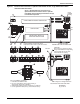
8.1 STANDARD ELECTRICAL CONNECTIONS
Source: DPN000807, Rev. 8
1. Primary high voltage entrance—2.5" (64mm); 1.75" (44mm); 1.375" (35mm) diameter
concentric knockouts located in bottom of box.
2. Secondary high voltage entrance—2.5" (64mm); 1.75" (44mm); 1.375" (35mm) diameter
concentric knockouts located in top of box.
3. Primary low voltage entrance—Quantity (3) 1.375" (35mm) diameter knockouts located in
bottom of unit.
4. Secondary low voltage entrance—Quantity (3) 1. 375" (35mm) diameter knockouts located in
top of box.
5. Three-phase electrical service—Terminals are on main fuse block (disregard if unit has
optional disconnect switch). Three-phase service not by Emerson.
6. Earth ground—Terminal for field-supplied earth grounding wire. Earth grounding required for
Liebert units.
7. Remote unit shutdown—Replace existing jumper between Terminals 37 & 38 with
field-supplied normally closed switch having a minimum 75VA, 24VAC rating. Use field-supplied
Class 1 wiring.
8. Customer alarm inputs—Terminals for field-supplied, normally open contacts, having a
minimum 75VA, 24VAC rating, between Terminals 24 & 50, 51, 55 & 56. Use field-supplied
Class 1 wiring. Terminal availability varies by unit options.
9. Common alarm—On any alarm, normally open dry contact is closed across Terminals 75 & 76
for remote indication. 1A, 24VAC maximum load. Use Class 1 field-supplied wiring.
10. Heat rejection interlock—On any call for compressor operation, normally open dry contact is
closed across Terminals 70 & 71 (Circuit 1), 230 (Circuit 2) to heat rejection equipment. 1A,
24VAC maximum load. Use field-supplied Class 1 wiring. When a Liebert DS unit is paired with a
Liebert MC series condenser, remove jumper between Terminal 71 and Terminal 230. Three
wires must connect Terminals 70, 71 and 230 of the indoor unit to Terminals 70, 71 and 230 of the
Liebert MC series condenser.
8.2 OPTIONAL ELECTRICAL CONNECTIONS
Source: DPN000807, Rev. 8
11. Unit factory installed disconnect switch, Fuse Block and Main Fuses—Two types of
disconnect switches are available: Non-Locking and Locking. The Non-Locking Type consists of a
non-automatic molded case switch operational from the outside of the unit. Access to the
high-voltage electric panel compartment can be obtained with the switch in either the On or Off
position. The Locking Type is identical except access to the high-voltage electric panel
compartment can be obtained only with the switch in the Off position. Units with fused
disconnects are provided with a defeater button that allows access to the electrical panel when
power is On. The molded case switch disconnect models contain separate main fuses. Units with
fused disconnect have main fuses within the disconnect. Only fused disconnects are used on dual
disconnect options.
12. Secondary disconnect switch and earth ground
13. Three-phase electrical service—Terminals are on top of disconnect switch. Three-phase
service not by Emerson.
14. Smoke sensor alarm—Factory-wired dry contacts from smoke sensor are 91-common, 92-NO,
and 93-NC. Supervised contacts, 80 & 81, open on sensor trouble indication. This smoke sensor is
not intended to function as or replace any room smoke detection system that may be required by
local or national codes. 1A, 24VAC maximum load. Use field-supplied Class 1 wiring.
15. Reheat and humidifier lockout—Remote 24VAC required at Terminals 82 & 83 for lockout of
reheat and humidifier.
16. Condensate alarm (with condensate pump option)—On pump high water indication,
normally open dry contact is closed across Terminals 88 & 89 for remote indication. 1A, 24VAC
maximum load. Use field-supplied Class 1 wiring.