
User manual

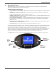

Table Of Contents
- Important Safety Instructions
- 1.0 Installation Instructions
- 1.1 Unpacking and Installation
- 1.2 Additional Distribution Mounting and Wiring
- 1.3 Power and Control Wiring
- 1.3.1 Input Power Connections
- Figure 5 Electrical connection location for 23" (584mm) cabinet
- Figure 6 Electrical connection location for 47" (1194mm) cabinet
- Figure 7 Electrical connection location for 47" cabinet with Square D I-Line panelboard
- Table 4 Suggested minimum input wire size data
- Table 5 Main input circuit breaker interrupting rating
- 1.3.2 Junction Box Installation
- Table 6 Main input junction box electrical connections (4 wire)
- Table 7 Main input junction box without transformer electrical connections (5 wire)
- Table 8 Low-voltage (control) junction box dimensions, typical
- Table 9 Main input (power) junction box dimensions, typical
- Figure 8 Low-voltage control junction box connections, typical
- Figure 9 Main input junction box connections, typical
- 1.3.3 System Grounding
- 1.3.4 Grounding Electrode Conductor for Liebert® FPCs With Transformer
- 1.3.5 Output Power Connections
- 1.3.6 Control Wiring Connections
- 1.3.7 Adapter Board
- 1.3.1 Input Power Connections
- 2.0 Equipment Inspection and Startup
- 3.0 Inspection and Startup Checklist
- 4.0 Operating Instructions
- 5.0 Maintenance

Operating Instructions
36
The following metering parameters may be displayed:
• Voltage - Line-to-Line
• Voltage - Line-to-Neutral
• Neutral Current
• Ground Current
•kVA
• Power Factor
• Voltage Total Harmonic Distortion (THD)
• Current Total Harmonic Distortion (THD)
• Crest Factor
Circuit identification and status of each breaker may be displayed.
The Liebert CPM detects and annunciates by alarm message the following conditions:
•Overvoltage
• Undervoltage
• Neutral Overcurrent
• Ground Overcurrent
• Phase Overcurrent
• Phase Overcurrent Warning
• Summary Alarm
All alarm thresholds for monitored parameters are adjustable by way of the DB-9 setup port to match
site requirements. The factory setpoints for the alarms are as follows:
• Overvoltage - at least one of the line-to-line voltages exceeds +6% of nominal
• Undervoltage - at least one of the line-to-line or line-to-neutral voltages falls below -13% of
nominal
• Phase Overcurrent Warning - current exceeds 75% of breaker amps
• Phase Overcurrent - current exceeds 80% of breaker amps
• Neutral Current - current exceeds 95% of breaker amps
• Ground Current - current exceeds 5 amps
Summary Alarm
• Summary Alarm - detects and annunciates any alarm.
Summary Alarm Contacts
• The CPM has a form C (one NO and one NC) summary alarm contacts for remote alarm status.
The contacts are rated at 24VAC @ 1A. There is one alarm contact per breaker. The contacts
change state upon occurrence of any alarm including warnings and reset when the alarm is
cleared. Summary alarm contacts are on the adapter board. The adapter board is on top of the
monitoring enclosure. See Figure 15 for details.
Communication - Liebert IntelliSlot
®
cards provide customer connections to a Building
Management System (BMS) or Remote Monitoring Systems. The following cards are available:
• IS-WEBS Card - Provides SNMP/WEB output. An RJ-45 connector is supplied for customer
connection to Ethernet LAN.
• IS-485S Card - Provides Modbus 485 output. A terminal strip is provided for two-wire connection.
• IS-IPBMS Card - Provides Modbus IP output. An RJ-45 connector is supplied for customer
connection. Up to three cards can be plugged into the Liebert IntelliSlot ports provided with the
VPMP system.
If communication to Liebert SiteScan
®
is required, customer connection can be made to the adapter
board RS-485 terminals on TB1, see Figure 15 for details. The adapter board is on top of the
monitoring enclosure.