Liebert® GXT4™ 230V, 5000-10,000VA User Manual
TABLE OF CONTENTS IMPORTANT SAFETY PRECAUTIONS . . . . . . . . . . . . . . . . . . . . . . . . . . . . . . . . . . . . . . . . . . . . . . . .1 GLOSSARY OF SYMBOLS . . . . . . . . . . . . . . . . . . . . . . . . . . . . . . . . . . . . . . . . . . . . . . . . . . . . . . .3 1.0 PRODUCT DESCRIPTION . . . . . . . . . . . . . . . . . . . . . . . . . . . . . . . . . . . . . . . . . . . . . . . . . . .4 1.1 Features . . . . . . . . . . . . . . . . . . . . . . . . . . . . . . . . . . . . . . . . . . . . . . .
3.4 Menu Structure . . . . . . . . . . . . . . . . . . . . . . . . . . . . . . . . . . . . . . . . . . . . . . . . . . . . . . . . . . . . 18 3.4.1 3.4.2 3.4.3 3.4.4 3.4.5 3.4.6 Startup Screen . . . . . . . . . . . . . . . . . . . . . . . . . . . . . . . . . . . . . . . . . . . . . . . . . . . . . . . . . . . . . . Default Screen . . . . . . . . . . . . . . . . . . . . . . . . . . . . . . . . . . . . . . . . . . . . . . . . . . . . . . . . . . . . . . Main Menu Screen . . . . . . . . . . . . . . . . . . .
FIGURES Figure 1 Figure 2 Figure 3 Figure 4 Figure 5 Figure 6 Figure 7 Figure 8 Figure 9 Figure 10 Figure 11 Figure 12 Figure 13 Figure 14 Figure 15 Figure 16 Figure 17 Figure 18 Figure 19 Figure 20 Figure 21 Figure 22 Figure 23 Figure 24 Figure 25 Figure 26 Figure 27 Figure 28 Figure 29 Figure 30 Figure 31 Figure 32 Figure 33 Figure 34 Figure 35 Figure 36 Figure 37 Figure 38 Figure 39 Figure 40 Figure 41 Figure 42 Figure 43 Figure 44 Liebert GXT4 5000VA and 6000VA, front view . . . . . . . . . . . . . . .
TABLES Table 1 Table 2 Table 3 Table 4 Table 5 Table 6 Table 7 Table 8 Table 9 Table 10 Table 11 Table 12 Table 13 Table 14 Table 15 Table 16 UPS models, power ratings . . . . . . . . . . . . . . . . . . . . . . . . . . . . . . . . . . . . . . . . . . . . . . . . . . . . . . . . 4 Branch circuit breaker ratings . . . . . . . . . . . . . . . . . . . . . . . . . . . . . . . . . . . . . . . . . . . . . . . . . . . . . 15 Electrical specifications . . . . . . . . . . . . . . . . . . . . . . . . . . . . . . . .
IMPORTANT SAFETY PRECAUTIONS ! WARNING Risk of electric shock. Can cause equipment damage, injury or death. Observe all cautions and warnings in this manual. Failure to do so may result in serious injury or death. Refer all UPS and battery service to properly trained and qualified service personnel. Do not attempt to service this product yourself.
! WARNING Risk of electric shock. Can cause equipment damage, injury and death. A battery can present a risk of electrical shock and high short-circuit current. The following precautions should be observed when working on batteries: • Remove watches, rings and other metal objects. • Use tools with insulated handles. • Wear rubber gloves and boots. • Do not lay tools or metal parts on top of batteries. • Disconnect charging source prior to connecting or disconnecting battery terminals.
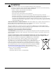
GLOSSARY OF SYMBOLS Risk of electrical shock ! Indicates caution followed by important instructions AC input AC output i - Requests the user to consult the manual + Indicates the unit contains a valve-regulated lead acid battery PbH2SO4 R Recycle DC voltage Equipment grounding conductor Bonded to ground AC voltage WEEE 3 Liebert® GXT4™
Product Description 1.0 PRODUCT DESCRIPTION The Liebert GXT4 is a compact, online uninterruptible power system (UPS) that continuously conditions and regulates its output voltage. The UPS is designed to supply microcomputers and other sensitive electronic equipment with clean sine wave input power, 5000VA, 6000VA and 10,000VA at 230V. Upon generation, AC power is clean and stable.
Product Description 1.3 Appearance and Components 1.3.1 Appearance The Liebert GXT4 rack/tower models in various power ratings have the same general appearance, controls and features (see Figure 1). The various rack/tower models differ largely in the type of receptacles each has. Figure 1 Liebert GXT4 5000VA and 6000VA, front view Upper Bezel 10,000VA model front layout is identical. The 10,000VA unit’s battery compartment is larger.
Product Description 1.3.
Product Description 1.4 Internal Battery Packs The UPS has two internal battery packs behind a battery access door on the front of the unit. Each internal battery pack is fitted with a connector to link to the UPS. Figure 4 Internal battery pack with connector Battery Handle GXT4 10,000 Battery Pack shown; 5000 and 6000VA battery packs have same features Battery Connector Front of Battery Pack 1.5 Removable Power Distribution Box The UPS arrives with a power distribution pack installed.
Product Description 1.6 Major Components General Outlet POD Dependent Dynamic Bypass L N G TVSS EMI/RFI Input Filter Rectifier/ PFC DC-DC Converter Inverter L EMI/RFI N Output Filter G Battery Charger General Outlet POD Dependent General Outlet POD Dependent General Outlet POD Dependent Battery The UPS is composed of mains input, TVSS and EMI/RFI filters, rectifier/PFC, inverter, battery charger, DC-to-DC converter, battery, dynamic bypass and UPS output. 1.6.
Product Description 1.6.6 Battery The Liebert GXT4 utilizes valve-regulated, nonspillable, lead acid batteries. To maintain battery design life, operate the UPS in an ambient temperature of 15°C to 25°C (59°F to 77°F). Optional external battery cabinets are available to extend battery run times. For run times, see Table 16. 1.6.7 Internal Bypass The Liebert GXT4 provides an alternate path for mains power to the connected load in the unlikely event of a UPS malfunction.
Product Description 1.7.3 Battery Mode The Liebert GXT4 enters Battery Mode when mains power fails or is outside acceptable limits. The battery system supplies power through the DC-to-DC converter to the inverter to generate clean AC power for the connected loads. When the Liebert GXT4 enters Battery Mode, the UPS sounds a half-second beep at 10-second intervals.
Installation 2.0 INSTALLATION Do NOT attempt to start the UPS, turn On any circuit breaker or energize the input power until instructed to do so in 4.2 - Starting the UPS. 2.1 Unpacking and Inspection Unpack the UPS and conduct the following checks: • Inspect the UPS for shipping damage. Report any shipping damage to the carrier and your local dealer or Emerson® representative immediately. • Check the accessories against the delivery list.
Installation 2.4 Install the Main Cabinet The Liebert GXT4 may be installed in either a tower configuration or in a rack, depending on available space and use considerations. Determine the type of installation and follow the appropriate instructions in either 2.4.1 - Tower UPS Installation or 2.4.2 - Rack Installation. 2.4.1 Tower UPS Installation To install the Liebert GXT4 as a tower: 1. Take out support bases from the accessories bag (see Figure 7).
Installation 2.4.2 Rack Installation The Liebert GXT4 UPS and external battery cabinets (EBC), when installed in a rack enclosure, must be supported by a shelf or rack-mount rails. The Liebert GXT4 UPS and EBC units ship with all required hardware to allow rack-mount installation (not included with model numbers that end in “E”). Because different rack-mount options install differently, refer to the installation instructions provided with the rack-mount kit being used. 2.4.
Installation NOTE When removing the External Battery Cabinet, the circuit breaker on the rear of the cabinet must be turned Off before disconnecting the cable. NOTE If the UPS is to be shipped or stored for an extended time, the connector should be disconnected. This will minimize any standby current drain on the batteries and help attain their design life. 2.
Installation 2.5.1 Distribution Box Electrical Connections Electrical connections are made through a removable power distribution box that attaches to the rear of the UPS. • PD2-CE6HDWRMBS fits the 5000 and 6000VA models of the Liebert GXT4 • PD2-CE10HDWRMBS fits the 10,000VA model of the Liebert GXT4 The installer must provide an upstream branch circuit breaker.
Installation 2.6 IT Power System Configuration 1. Remove screws on the IT Power System Access Cover as shown in Figure 14. 2. Disconnect the connectors as shown in figure. 3. Install IT Power System Access Cover and screws.
Operation and Display Panel 3.0 OPERATION AND DISPLAY PANEL This chapter describes the Liebert GXT4 controls, particularly the operation and display panel on the front of the Liebert GXT4. The panel has four control buttons, seven LED indicators and a liquid crystal display (LCD), as shown in Figure 15. Figure 15 Operation and display panel Inverter Indicator Battery Indicator Bypass Indicator Fault Indicator LCD Panel ECO mode Indicator ENTER Button ESC Button UP Arrow Button 3.
Operation and Display Panel 3.2 Control Buttons The four control buttons on the front of the operation and display panel are: • • • • ESC Up Down Enter Figure 15 shows the buttons’ locations; their descriptions and functions are shown in Table 5. Table 5 3.3 Control buttons Control Buttons Description ESC Button Pressing this button returns to the previous menu or aborts any change in the input data field before confirming.
Operation and Display Panel Figure 16 Menu structure Audible Alarm Output Startup on Bypass Load Status UPS Battery Enable Auto Restart Time Since Startup Frequency Selection Start Windows System Status Enable Auto Shutdown Input Output Level Selection Configuration Parallel Selection Turn UPS On/Off Turn UPS On Turn UPS Off Battery Cabinets BATT Main Menu Control Alarm Control 1. Audible Alarm On 2. Audible Alarm Off Batt Test 1. Start 2. Cancel 3.
Operation and Display Panel 3.4.1 Startup Screen When the Liebert GXT4 is starting up, it initiates a self-test and displays the screen shown in Figure 17 for about 10 seconds. Figure 17 Startup screen EMERSON Network Power After about 10 seconds, the LCD shows one of the On screens in Figure 18; the screen shown depends on whether input power is available. Figure 18 Startup screens TURN ON UPS YES NO O/P: 0V HZ 0.0A I/P : 230 V 50HZ 0.
Operation and Display Panel 3.4.2 Default Screen Press any button in the START SUCCESSFUL screen to enter the default interface, shown in Figure 20. Figure 20 Default screen GXT4-UPS 3KVA Values shown will vary according to installation and configuration. O/P: 230V 50HZ 11.7A I /P: 230V 50HZ 13.1A BATT: 100 % 3MINS LOAD: 100% In the default screen, the LCD shows the UPS model, output parameters, input parameters, battery capacity with run time estimate and load percentage.
Operation and Display Panel Figure 22 Status screens OUTPUT LOAD VOLTAGE : 120V FREQUENCY : 60HZ CURRENT : 17.6A POWER : 2112 KWH CAP : WATT : VA : INPUT VOLT FREQ CURR POWER 90% 1620W 1800VA : : : : 120V 60 HZ 18.6A 97KWH BATTERY TIME SINCE STARTUP CAPACITY : RUNTIME : VOLTAGE : 90% 100 MINS 80V 05D 15H 30M CONFIGURATION Screen Select MAIN MENU > CONFIGURATION to enter the Configuration menu. This menu has seven submenus, as shown in Figure 23. Figure 23 CONFIGURATION screen 1. 2. 3. 4. 5.
Operation and Display Panel UPS Screen Select MAIN MENU > CONFIGURATION > UPS to enter the UPS screen. This menu has six screens, as shown in Figure 24. Figure 24 UPS screens AUDIBLE ALARM STARTUP ON BYPASS GUARANTEE SHUTDOWN OFF NO NO ENABLE AUTO RESTART FREQUENCY SELECTION VOLTAGE SELECTION YES AUTO - BYPASS ENABLE 230 Press the Up or Down button to move the cursor to the required item, and press the Enter button to confirm the settings.
Operation and Display Panel Battery Screen Select MAIN MENU > CONFIGURATION > BATTERY to enter the BATTERY screen. This menu has four screens, as shown in Figure 26. Figure 26 Battery screen EXT BATT CABINET 0 LOW BATTERY TIME CABINETS 2 BATT TEST INTERVAL 8 MINS BATT REPLACE TIME WEEKS 2014 Y 1M 1D Press the Up or Down button to increase or decrease the value of the settings, and press the Enter button to confirm it.
Operation and Display Panel LCD Screen Select MAIN MENU -> 2 CONFIGURATION -> 6 LCD to enter the LCD screen. This menu has two submenus, as shown in Figure 28. Figure 28 LCD screen 1 LANGUAGE 2 COLOR Select ‘1 LANGUAGE’ and press the Enter button to enter the LANGUAGE screen, as shown in Figure 29. The Liebert GXT4 is capable of supporting multiple languages. For the list of supported languages and instructions on how to upload them, refer to the Configuration Program user manual on the included CD.
Operation and Display Panel FACTORY DEFAULT Screen Select MAIN MENU -> 2 CONFIGURATION -> 7 FACTORY DEFAULT to enter the FACTORY DEFAULT screen, as shown in Figure 31. Figure 31 Factory Default screen RESET ALL SETTINGS TO FACTORY DEFAULT SETTINGS? YES NO Control Screen Select MAIN MENU -> 3 CONTROL to enter the CONTROL screen. This screen has three submenus, as shown in Figure 32.
Operation and Display Panel ALARM CONTROL Screen Select MAIN MENU -> 3 CONTROL -> 2 ALARM CONTROL to enter the ALARM CONTROL screen, as shown in Figure 34. This section allows active audible alarms to be silenced. To completely turn off the audible alarm, refer to CONFIGURATION > UPS as shown in Figure 24. Figure 34 Alarm Control screen 1 AUDIBLE ALARM ON 2 AUDIBLE ALARM OFF BATT TEST Screen Select MAIN MENU -> 3 CONTROL -> 3 BATT TEST to enter the BATT TEST screen, as shown in Figure 35.
Operation and Display Panel CLEAR LOG Screen Select MAIN MENU > LOG > CLEAR LOG to enter the CLEAR LOG screen, as shown in Figure 37. Figure 37 Clear Log screen DO YOU WANT TO CLEAR EVENT LOGS? YES NO Press the Up or Down button to move the cursor to the required item. Press the Enter button to confirm the settings. ABOUT Screen Select MAIN MENU> ABOUT to enter the ABOUT screen, as shown in Figure 38.
Operation and Display Panel Figure 39 Network screens ADDRESS MAC ADDRESS IPV4 ADDRESS IPV6 STATIC 00-02-11-4X-AX 10.163.226 .231 /24 :: ADDRESS IPV6 LINK ADDRESS IPV6 AUTO Fe80::202:99ff:fe0f:4ba 2%1 :: 3.4.4 Prompt List A prompt screen is displayed during the operation of the system to alert to certain conditions and/or to require confirmation of a command or other operation. The prompts and meanings are given in Table 6.
Operation and Display Panel 3.4.5 Warning List All UPS warning messages are described in Table 7. Table 7 3.4.6 Warning list Warning Description Utility power not available The utility power is not available, or it cannot satisfy the requirements for the UPS to operate UPS batteries low and exhausted soon The battery capacity is low and will be exhausted soon.
Operation 4.0 OPERATION This section describes checks to be made before starting the UPS, how to start the UPS, manual battery test, manual bypass, shutting down the UPS and disconnecting mains power from the UPS. NOTE The Liebert GXT4’s battery has been fully charged before delivery, but some charge will be lost during storage and shipping. To ensure that the battery has adequate reserve power to protect the connected load, charge the battery for three hours before putting the UPS into service. 4.
Operation 4.6 Disconnecting Input Power from the Liebert GXT4 1. After the UPS has been shut down as detailed in 4.5 - Shut Down the Liebert GXT4, disconnect the input cable from the wall socket. 2. Wait 30 seconds and verify that all indicators have turned Off and the fan has stopped; this indicates that the power-Off is complete. 3. Turn the external battery cabinet breaker switch to the Off position if the UPS has an external battery cabinet.
Communication 5.0 COMMUNICATION This section describes the three types of communication ports on the rear of the UPS: • Liebert IntelliSlot® port • USB port (standard B-type) • Terminal Block Communication ! CAUTION To maintain safety (SELV) barriers and for electromagnetic compatibility, signal cables should be segregated and run separate from all other power cables. 5.
Communication 5.2.1 Configuration Program The configuration program is on the Liebert GXT4 CD and can be used instead of making configuration setting changes from the LCD panel. The configuration program communicates to a computer running a Microsoft® Windows® operating system via the included USB cable. For most users, the factory default settings are adequate. This section give a brief overview of the features and parameters that are available for modification, as well as the factory default settings.
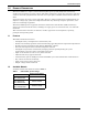
Communication 5.3 Terminal Block Communication The Terminal Block includes eight pins, as shown in Figure 40. Figure 40 Terminal Block Communication pin layout 5.3.1 1 2 Any Mode Shutdown 3 4 Battery Mode Shutdown 5 6 On Battery Mode 7 8 Low Battery Any Mode Shutdown The purpose of Any Mode Shutdown is to shut down the UPS output by turning Off the rectifier, inverter and static switch so that there is no power to the loads.
Communication 5.3.2 Battery Mode Shutdown Battery Mode Shutdown permits shutting down the UPS by turning Off the rectifier, inverter and static switch so that there is no power to the load when the UPS is On Battery. The auxiliary power for the UPS will still be active. Battery Mode Shutdown can be performed locally or remotely: • Local Battery Mode shutdown can be performed by shorting Pin3 and Pin4.
Communication 5.4 Remote Emergency Power Off The UPS is equipped with a Remote Emergency Power Off (REPO) connector. The user must supply a means of interfacing with the REPO circuit to allow disconnecting the UPS input feeder breaker to remove all sources of power to the UPS and connected equipment to comply with national and local wiring codes and regulations.
Maintenance 6.0 MAINTENANCE This section describes replacing the internal battery pack, precautions, checking the Liebert GXT4’s status and checking UPS functions. 6.1 Replacing the Internal Battery Pack The Liebert GXT4 is designed to allow the user to replace the internal battery pack safely. Read the safety cautions before proceeding. Contact your local dealer or Emerson® representative to obtain the pricing of the appropriate replacement battery pack. 6.1.
Maintenance 5. Grasp the battery handle and pull one of the internal battery packs out of the UPS, as shown in Figure 44. Repeat this step if both battery packs will be replaced. Each model has two battery packs Figure 44 Pulling out the battery packs 10,000VA model 5000 & 6000 VA models Internal Battery Pack Internal Battery Pack Battery Handle Battery Handle Pull Out with Battery Handle Each model has two battery packs Pull Out with Battery Handle 6. Unpack a new internal battery pack.
Maintenance 6.4 Checking UPS Status Emerson® recommends checking the UPS operation status every six months. • Check whether the UPS is faulty: Is the Fault Indicator On? Is the UPS sounding an alarm? • Check whether the UPS is operating in Bypass Mode. Normally, the UPS operates in Normal Mode. If it is operating in Bypass Mode, stop and contact your local Emerson representative, or Emerson Channel Support. • Check whether the battery is discharging.
Troubleshooting 7.0 TROUBLESHOOTING This section indicates various UPS symptoms a user may encounter and provides a troubleshooting guide in the event the UPS develops a problem. Use the following information to determine whether external factors caused the problem and how to remedy the situation. 7.1 UPS Symptoms The following symptoms indicate the Liebert GXT4 is malfunctioning: • The relative indicators illuminate, indicating the UPS has detected a problem.
Troubleshooting 7.1.2 Audible Alarm An audible alarm will sound in conjunction with the visual indicators to indicate a change in UPS operating status. The audible alarm will sound as described in Table 11.
Specifications 8.0 SPECIFICATIONS Table 13 UPS specifications Model # Rating GXT4-5000RT230 GXT4-5000RT230E GXT4-6000RT230 GXT4-6000RT230E GXT4-10000RT230 GXT4-10000RT230E 5000VA/4000W 6000VA/4800W 10,000VA/9000W Dimensions, mm (in) Unit, W x D x H 430 x 574 x 217 (16.9 x 22.4 x 8.5) 430 x 581 x 261 (16.9 x 22.9 x 10.3) Shipping, W x D x H 516 x 745 x 530 (20.3 x 29.3 x 20.9) 530 x 745 x 563 (20.9 x 29.3 x 22.2) Weight, kg (lb) Unit Shipping 60 (132.2) 70 (154.3) 75 (165.
Specifications Table 13 UPS specifications (continued) GXT4-5000RT230 GXT4-5000RT230E Model # GXT4-6000RT230 GXT4-6000RT230E GXT4-10000RT230 GXT4-10000RT230E Bypass Protection Limits Disable Bypass Operation Re-Enable Bypass Operation If input voltage exceeds ±15% of the nominal voltage If input voltage returns to within ±10% of nominal output voltage Disable Bypass operation When the input frequency prevents synchronous operation Environmental Operating Temperature, °C (°F) 0 to 40 (32 to 104) (
Specifications Table 15 External battery cabinet specifications GXT4-240VBATT Model Number GXT4-5000RT230; GXT4-6000RT230; GXT4-10000RT230 Used with UPS Model Dimensions, W x D x H, mm (in.) Unit (with bezel) Shipping 430 x 581 x 173 (16.9 x 22.9 x 6.8) 530 x 745 x 475 (20.9 x 29.3 x 18.7) Weight, kg (lb) Unit Shipping 65 (143.3) 80 (176.4); “E” models 76 (167.
Specifications Table 16 Battery run time, minutes, all models Number of Batteries/Cabinets Internal Battery Internal Battery + 1 External Battery Cabinet Internal Battery + 2 External Battery Cabinets Internal Battery + 3 External Battery Cabinets Liebert® GXT4™ 230VAC RT Models Load Percent of Capacity 5kVA 6kVA 10kVA 10% 105 97 98 20% 52 47 42 30% 40 33 25 40% 27 22 17 50% 21 17 12 60% 17 14 9 70% 14 11 7 80% 12 9 6 90% 10 8 5 100% 9 6 4 10% 211 194
Specifications Table 16 Battery run time, minutes, all models (continued) Number of Batteries/Cabinets Internal Battery + 4 External Battery Cabinets Internal Battery + 5 External Battery Cabinets Internal Battery + 6 External Battery Cabinets 230VAC RT Models Load Percent of Capacity 5kVA 6kVA 10kVA 10% 480 463 436 20% 428 338 213 30% 312 227 153 40% 209 166 127 50% 164 150 99 60% 151 134 77 70% 138 113 64 80% 124 103 51 90% 108 92 47 100% 100 78 42 10%
Specifications 8.1 Auto-Learning Battery Run Times As batteries age, the estimated run times may become less accurate. The Liebert GXT4 is programmed to “learn” from a full battery discharge and modify the estimated runtime for the measured battery capacity. This can improve accuracy and compensate for aging batteries or batteries that operate at different ambient temperatures. The UPS will update the anticipated run time calculation only under certain conditions.
Technical Support / Service Web Site www.liebert.com Monitoring liebert.monitoring@emerson.com 800-222-5877 Outside North America: +00800 1155 4499 Single-Phase UPS & Server Cabinets liebert.upstech@emerson.