Liebert® GXT4™ UPS 230V 700VA-3000VA User Manual
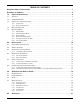
TABLE OF CONTENTS IMPORTANT SAFETY PRECAUTIONS . . . . . . . . . . . . . . . . . . . . . . . . . . . . . . . . . . . . . . . . . . . . . . . .1 GLOSSARY OF SYMBOLS . . . . . . . . . . . . . . . . . . . . . . . . . . . . . . . . . . . . . . . . . . . . . . . . . . . . . . . .3 1.0 PRODUCT DESCRIPTION . . . . . . . . . . . . . . . . . . . . . . . . . . . . . . . . . . . . . . . . . . . . . . . . . . .4 1.1 Features . . . . . . . . . . . . . . . . . . . . . . . . . . . . . . . . . . . . . . . . . . . . . .
.1 Startup Checklist for the Liebert GXT4 . . . . . . . . . . . . . . . . . . . . . . . . . . . . . . . . . . . . . . . . . 31 4.2 Starting the UPS . . . . . . . . . . . . . . . . . . . . . . . . . . . . . . . . . . . . . . . . . . . . . . . . . . . . . . . . . . . 31 4.3 Manual Battery Test . . . . . . . . . . . . . . . . . . . . . . . . . . . . . . . . . . . . . . . . . . . . . . . . . . . . . . . . 31 4.4 Manual Bypass . . . . . . . . . . . . . . . . . . . . . . . . . . . . . . . . . . . . . . .
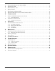
FIGURES Figure 1 Figure 2 Figure 3 Figure 4 Figure 5 Figure 6 Figure 7 Figure 8 Figure 9 Figure 10 Figure 11 Figure 12 Figure 13 Figure 14 Figure 15 Figure 16 Figure 17 Figure 18 Figure 19 Figure 20 Figure 21 Figure 22 Figure 23 Figure 24 Figure 25 Figure 26 Figure 27 Figure 28 Figure 29 Figure 30 Figure 31 Figure 32 Figure 33 Figure 34 Figure 35 Figure 36 Figure 37 Figure 38 Figure 39 Figure 40 Figure 41 Figure 42 Figure 43 Figure 44 Liebert GXT4-700RT230 - GXT4-3000RT230 UPS . . . . . . . . . . . . . . .
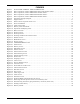
TABLES Table 1 Table 2 Table 3 Table 4 Table 5 Table 6 Table 7 Table 8 Table 9 Table 10 Table 11 Table 12 Table 13 Table 14 Table 15 Table 16 Table 17 Table 18 Table 19 UPS models, power ratings . . . . . . . . . . . . . . . . . . . . . . . . . . . . . . . . . . . . . . . . . . . . . . . . . . . . . . . . 4 Input circuit breaker specifications . . . . . . . . . . . . . . . . . . . . . . . . . . . . . . . . . . . . . . . . . . . . . . . . . 12 Type of cord . . . . . . . . . . . . . . . . . . . . . . . . . .
IMPORTANT SAFETY PRECAUTIONS ! WARNING Risk of electric shock. Can cause equipment damage, injury or death. Observe all cautions and warnings in this manual. Failure to do so may result in serious injury or death. Refer all UPS and battery service to properly trained and qualified service personnel. Do not attempt to service this product yourself.
! WARNING Risk of electric shock. Can cause equipment damage, injury and death. A battery can present a risk of electrical shock and high short-circuit current. The following precautions should be observed when working on batteries: • Remove watches, rings and other metal objects. • Use tools with insulated handles. • Wear rubber gloves and boots. • Do not lay tools or metal parts on top of batteries. • Disconnect charging source prior to connecting or disconnecting battery terminals.
GLOSSARY OF SYMBOLS Risk of electrical shock ! Indicates a warning or a caution followed by important instructions AC input AC output i - Requests the user to consult the manual + Indicates the unit contains a valve-regulated lead acid battery PbH2SO4 R Recycle DC voltage Equipment grounding conductor Bonded to ground AC voltage WEEE 3 Liebert® GXT4™
Product Description 1.0 PRODUCT DESCRIPTION The Liebert GXT4 is a compact, online uninterruptible power system (UPS) that continuously conditions and regulates its output voltage. The UPS is designed to supply microcomputers and other sensitive electronic equipment with clean sine wave input power, 700VA to 3000VA at 230V. Upon generation, AC power is clean and stable.
Product Description 1.3 Appearance and Components 1.3.1 Appearance The Liebert GXT4 rack/tower models in various power ratings have the same general appearance, controls and features (see Figure 1). The various rack/tower models differ largely in the type of receptacles each has. Figure 1 Liebert GXT4-700RT230 - GXT4-3000RT230 UPS Ventilation Slots 1.3.
Product Description Figure 3 Rear components, Liebert GXT4 230V 1500VA models Liebert IntelliSlot Port USB Port Dry Contacts Figure 4 RS232 Port Fan External Battery Connector Outlet1 Receptacles (Programmable ) General Output Outlet2 Receptacles Programmable Rear components, Liebert GXT4 230V 2000VA models Liebert IntelliSlot Port USB Port Terminal Block Communications Figure 5 C14 Input Input Circuit Breaker RS232 Port Input Circuit Breaker Cooling Fan C20 Input External Battery Connec
Product Description 1.4 Major Components The operating principle of the UPS is shown in Figure 6.
Product Description DC-to-DC Converter The DC-to-DC converter raises the DC voltage from the battery to the optimum operating voltage for the inverter. This allows the inverter to operate continuously at its optimum efficiency and voltage, increasing reliability. Battery The Liebert GXT4 utilizes valve-regulated, nonspillable, lead acid batteries. To maintain battery design life, operate the Liebert GXT4 in an ambient temperature of 0°C to 25°C (32°F to 77°F).
Product Description 1.5.3 Battery Mode The Liebert GXT4 enters Battery Mode when mains power fails or is outside acceptable limits. The battery system supplies power through the DC-to-DC converter to the inverter to generate clean AC power for the connected loads. When the Liebert GXT4 enters Battery Mode, the UPS sounds a half-second beep at 10-second intervals.
Installation 2.0 INSTALLATION 2.1 Unpacking and Inspection Unpack the UPS and conduct the following checks: • Inspect the UPS for shipping damage. If any shipping damage is found, report it to the carrier and your local dealer or Emerson® representative immediately. • Check the accessories against the delivery list. If there is any discrepancy, contact your local dealer or your Emerson representative immediately. 2.
Installation Installation Clearances Maintain a clearance of at least 100mm (4 inches) in the front and rear of the Liebert GXT4. Do not obstruct the air inlets on the front panel or rear panel of the UPS—blocking the air inlets reduces ventilation and heat dissipation, shortening the service life of the Liebert GXT4. 2.4 Mechanical Installation The Liebert GXT4 may be installed as a tower or in a rack, depending on space and use considerations.
Installation 5. Place the Liebert GXT4 and any battery cabinets on the support bases. Each Liebert GXT4 needs four support bases, as shown in Figure 9. Figure 9 Tower installation Liebert GXT4 UPS and External Battery Cabinet Liebert GXT4 UPS Operation and Display Panel Rotated for Tower Operation Support Bases Support Bases 2.4.2 Rack Installation The Liebert GXT4 UPS and external battery cabinets (EBC), when installed in a rack enclosure, must be supported by a shelf or rack-mount rails.
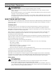
Installation For North America Installations Detachable Power Supply Cord Not Provided. Power Supply Cord Selection (for units which power supply cord not furnished with) - Use UL Listed detachable power supply cord, three conductors, minimum 4.5 ft. (1.5m), maximum 14.8 ft. (4.5m) long. Types SP-2, SP-3, SV and similar cords may be provided if the cord is not long. Refer to Tables 3 and 4 for details.
Installation 2.5.2 Connecting Battery Cables 1. Verify that the battery isolation breaker is in the Off (open) position. 2. Take out the battery cable included with the battery cabinet. 3. Connect one end of the battery cable to the external battery connector on the rear panel of the UPS, and connect the other end to any battery port on the rear panel of the battery cabinet. 4. Repeat Steps 1 through 3 for each battery cabinet that will be connected to the system.
Operation and Display Panel 3.0 OPERATION AND DISPLAY PANEL This chapter describes the Liebert GXT4 controls, particularly the operation and display panel on the front of the Liebert GXT4. The panel has four control buttons, seven LED indicators and a liquid crystal display (LCD), as shown in Figure 12.
Operation and Display Panel 3.2 Control Buttons The four control buttons on the front of the operation and display panel are: • • • • ESC Up Down Enter Figure 12 shows the buttons’ locations; their descriptions and functions are shown in Table 4. Table 4 3.3 Control buttons Control Buttons Description ESC Button Pressing this button returns to the previous menu or aborts any change in the input data field before confirming.
Operation and Display Panel 3.4 Menu Structure The menu structure of the LCD is shown in Figure 13. Figure 13 Menu structure Audible Alarm Output Startup on Bypass Load Status UPS Battery Enable Auto Restart Time Since Startup Frequency Selection Start Windows System Status Enable Auto Shutdown Input Output Level Selection Configuration Battery Cabinets Turn UPS On/Off Turn UPS On Turn UPS Off BATT Low Battery Time Warning Batt Test Interval Main Menu Control Alarm Control 1.
Operation and Display Panel 3.4.1 Startup Screen When the Liebert GXT4 is starting up, it initiates a self-test and displays the screen shown in Figure 14 for about 10 seconds. Figure 14 Startup screen EMERSON Network Power After about 10 seconds, the LCD shows one of the On screens in Figure 15; the screen shown depends on whether input power is available. Figure 15 Startup screens TURN ON UPS YES NO O/P: 0V HZ 0.0A I/P : 230 V 50HZ 0.
Operation and Display Panel 3.4.2 Default Screen Press any button in the START SUCCESSFUL screen to enter the default interface, shown in Figure 17. Figure 17 Default screen GXT4-UPS 3KVA Values shown will vary according to installation and configuration. O/P: 230V 50HZ 11.7A I /P: 230V 50HZ 13.1A BATT: 100 % 3MINS LOAD: 100% In the default screen, the LCD shows the UPS model, output parameters, input parameters, battery capacity with run time estimate and load percentage.
Operation and Display Panel Figure 19 Status screens OUTPUT LOAD VOLTAGE : 120V FREQUENCY : 60HZ CURRENT : 17.6A POWER : 2112 KWH CAP : WATT : VA : INPUT VOLT FREQ CURR POWER 90% 1620W 1800VA : : : : 120V 60 HZ 18.6A 97KWH BATTERY TIME SINCE STARTUP CAPACITY : RUNTIME : VOLTAGE : 90% 100 MINS 80V 05D 15H 30M CONFIGURATION Screen Select MAIN MENU > CONFIGURATION to enter the Configuration menu. This menu has seven submenus, as shown in Figure 20. Figure 20 CONFIGURATION screen 1. 2. 3. 4. 5.
Operation and Display Panel UPS Screen Select MAIN MENU > CONFIGURATION > UPS to enter the UPS screen. This menu has six screens, as shown in Figure 21. Figure 21 UPS screens AUDIBLE ALARM STARTUP ON BYPASS GUARANTEE SHUTDOWN OFF NO NO ENABLE AUTO RESTART FREQUENCY SELECTION VOLTAGE SELECTION YES AUTO - BYPASS ENABLE 230 Press the Up or Down button to move the cursor to the required item, and press the Enter button to confirm the settings.
Operation and Display Panel ECO Mode Screens Select MAIN MENU > CONFIGURATION > ECO MODE to enter the ECO MODE screens, as shown in Figure 23. Figure 23 ECO Mode screen ECO MODE VOLTAGE TOLERANCE ON 10% FREQUENCY TOLERANCE REQUALIFICATION TIME 3 Hz 5 MINS Press the Up or Down button to move the cursor to the required item, and press the Enter button to confirm the settings. Outlet1 Screen Select MAIN MENU > 2 CONFIGURATION > 4 OUTLET1 to enter the OUTLET1 screen.
Operation and Display Panel Select 1 OUTLET CONTROL and press the Enter button to enter the OUTLET CONTROL screen, as shown in Figure 25. Figure 25 Outlet Control screen OUTLET CONTROL OUTLET CONTROL TURN OFF REBOOT TURN ON Outlet Control is On Outlet Control is Off Press the Up or Down button to move the cursor to the required item, and press the Enter button to confirm the settings. Select 2 Outlet Setting and press the Enter button to enter the OUTLET SETTING screen, as shown in Figure 26.
Operation and Display Panel Outlet2 Screen The Outlet2 screens are the same as the Outlet1 screens. The same settings are available as on the Outlet1 screen. If the Outlet2 group will have the same settings as the Outlet1 group, the Liebert GXT4 offers a programming shortcut, as shown in Figure 27. When configuring the Outlet2 group, the select YES and press the Enter button to apply the Outlet1 settings to the Outlet2 screen.
Operation and Display Panel Select 2 COLOR and press the Enter button to enter the COLOR screen, as shown in Figure 30. Figure 30 Color screen EMERSON EMERSON EMERSON EMERSON FACTORY DEFAULT screen Select MAIN MENU -> 2 CONFIGURATION -> 7 FACTORY DEFAULT to enter the FACTORY DEFAULT screen, as shown in Figure 31. Figure 31 Factory Default screen RESET ALL SETTINGS TO FACTORY DEFAULT SETTINGS? YES NO Control Screen Select MAIN MENU -> 3 CONTROL to enter the CONTROL screen.
Operation and Display Panel TURN ON & OFF screen Select MAIN MENU -> 3 CONTROL -> 1 TURN ON & OFF to enter the TURN ON & OFF screen. This screen shows one of two displays, depending on the state of the UPS, as shown in Figure 33. Figure 33 Turn UPS On or Off screen TURN OFF UPS TURN ON UPS BYPASS TURN ON UPS UPS is Off UPS is On ALARM CONTROL screen Select MAIN MENU -> 3 CONTROL -> 2 ALARM CONTROL to enter the ALARM CONTROL screen, as shown in Figure 34.
Operation and Display Panel Log Screen Select MAIN MENU -> 4 LOG to enter the LOG screen. This screen has two submenus, as shown in Figure 36. Figure 36 Log screens 254 /255 1 VIEW LOG 2 CLEAR LOG 255 OD 1H 17m AGO UPS switch to Online mode CLEAR LOG Screen Select MAIN MENU > LOG > CLEAR LOG to enter the CLEAR LOG screen, as shown in Figure 37. Figure 37 Clear Log screen DO YOU WANT TO CLEAR EVENT LOGS? YES NO Press the Up or Down button to move the cursor to the required item.
Operation and Display Panel Network Select MAIN MENU>NETWORK to enter the NETWORK screen. The NETWORK screen displays the MAC address and the IPv4 IP address. If the Liebert GXT4 is fitted with an optional Liebert IntelliSlot Web card (Liebert IS-WEBCARD), the screen will display IPv6 IP address settings (IPv6 requires configuration), as shown in Figure 39. Figure 39 Network screens ADDRESS MAC ADDRESS IPV4 ADDRESS IPV6 STATIC 00-02-11-4X-AX 10.163.226 .
Operation and Display Panel 3.4.4 Prompt List A prompt screen is displayed during the operation of the system to alert you to certain conditions and/or to require your confirmation of a command or other operation. See Table 5 for the system prompts and meanings. Table 5 3.4.5 Prompts and meanings Prompt Meanings Mains Power Restored The mains power returns and the UPS transfers back to mains (AC) mode.
Operation and Display Panel 3.4.6 Fault List All UPS fault messages are described in Table 7. Table 7 Fault list Fault Description UPS Self-Test Failed The battery is bad or weak or not connected. UPS Overload The UPS is overloaded. Inverter Out Of Order The inverter has failed. Battery Weak/Bad The battery is bad or weak. Output Short Circuit The output connection is short-circuited. DC Bus Overvoltage The DC bus is faulty.
Operation 4.0 OPERATION This section describes checks to be made before starting the UPS, how to start the UPS, manual battery test, manual bypass, shutting down the UPS and disconnecting mains power from the UPS. NOTE The Liebert GXT4’s battery has been fully charged before delivery, but some charge will be lost during storage and shipping. To ensure that the battery has adequate reserve power to protect the connected load, charge the battery for three hours before putting the UPS into service. 4.
Operation 4.5 Shut Down the Liebert GXT4 To shut down the UPS from the LCD: 1. 2. 3. 4. From the Main Menu select CONTROL, press Enter, then select TURN ON & OFF. Press the enter key. Select TURN UPS OFF, then press Enter. Press either the Up or Down button to move the cursor to confirm the shutdown command and press Enter. The UPS will sound an audible alarm; this is normal. Power to the connected equipment is now Off. 5.
Communication 5.0 COMMUNICATION This section describes the four types of communication ports on the rear of the UPS: • • • • Liebert IntelliSlot® port USB port (standard B-type) Terminal Block Communication RS232 port (DB9F) ! CAUTION To maintain safety (SELV) barriers and for electromagnetic compatibility, signal cables should be segregated and run separate from all other power cables. 5.
Communication 5.2 USB Port Communication The standard B-type USB port is used to connect the UPS and network server or other computer system using Liebert MultiLink®. A standard B-type USB port is provided to allow connection to a computer or network server. The USB port can be used to communicate with the Liebert GXT4 configuration program (see section 5.2.1 for details) or Liebert MultiLink (refer to 5.1.1 - Liebert MultiLink for description) that is provided on the CD that is included with the UPS. 5.
Communication 5.3 RS-232 Port The RS-232 port uses an Emerson® proprietary protocol that is for use with Liebert MultiLink®. This port enables a more secure connection instead of the USB cable, to the computer or server that has Liebert MultiLink installed. 5.4 Terminal Block Communication The Terminal Block includes eight pins, as shown in Figure 40. Figure 40 Terminal Block Communication pin layout 5.4.
Communication 5.4.2 Battery Mode Shutdown Battery Mode Shutdown permits shutting down the UPS by turning Off the rectifier, inverter and static switch so that there is no power to the load when the UPS is On Battery. The auxiliary power for the UPS will still be active. Battery Mode Shutdown can be performed locally or remotely: • Local Battery Mode shutdown can be performed by shorting Pin3 and Pin4.
Maintenance 6.0 MAINTENANCE This section describes replacing the internal battery pack, precautions, checking the Liebert GXT4’s status and checking UPS functions. ! WARNING The battery can present a risk of electrical shock and high short circuit current. The following precautions should be observed before replacing the battery pack: • Remove rings, watches and other metal objects. • Use tools with insulated handles. • Do not lay tools or other metal objects on the batteries.
Maintenance 6.1.1 Battery Replacement Procedures 1. Gently remove the front plastic bezel cover from the UPS. 2. Loosen and remove the six screws on the battery door, as shown in Figure 41. 3. Lay the battery door and screws aside for reassembly. Figure 41 Removing the front plastic bezel cover and battery door 4. Gently pull the battery wire out and disconnect the battery plug and battery receptacle, as shown in Figure 42.
Maintenance 10. Reattach the front battery door with the six screws. 11. Reattach the front plastic bezel cover to the UPS. NOTE The internal battery pack is hot-swappable. However, caution should be exercised because during this procedure the load is unprotected from disturbances and power outages. Do not replace the battery while the UPS is in Battery Mode. This will result in a loss of output power and will drop the connected load. 6.
Troubleshooting 7.0 TROUBLESHOOTING This section indicates various UPS symptoms a user may encounter and provides a troubleshooting guide in the event the UPS develops a problem. Use the following information to determine whether external factors caused the problem and how to remedy the situation. 7.1 UPS Symptoms The following symptoms indicate the Liebert GXT4 is malfunctioning: • The relative indicators illuminate, indicating the UPS has detected a problem.
Troubleshooting 7.1.2 Audible Alarm An audible alarm will sound in conjunction with the visual indicators to indicate a change in UPS operating status. The audible alarm will sound as described in Table 11.
Battery Cabinet 8.0 BATTERY CABINET Optional battery cabinets are available for the Liebert GXT4. The external battery connector and isolation breaker are on the battery cabinet’s rear panel, as shown in Figure 44. For battery cabinet specifications, refer to Table 15.
Specifications 9.0 SPECIFICATIONS The specifications of the Liebert GXT4 are listed in Table 13 and Table 14.
Specifications Table 14 Specifications of the Liebert GXT4-1500RT230/230E, GXT4-2000RT230/230E and GXT-3000RT230/230E GXT4-1500RT230 GXT4-1500RT230E 1500VA/1350W Parameters Model Rating Dimensions, D x W x H, mm (in) Product model GXT4-2000RT230 GXT4-3000RT230 GXT4-2000RT230E GXT4-3000RT230E 2000VA/1800W 3000VA/2700W 497 × 430 × 85 (19.6 x 16.9 x 3.3) 617 x 570 x 262 (24.3 x 22.4 x 10.3) Unit Shipping 602 × 430 × 85 (23.7 x 16.9 x 3.3) 717 x 570 x 262 (28.2 x 22.4 x 10.
Specifications Table 15 Battery cabinet specifications Model Number Parameter GXT4-48VBATT GXT4-48VBATTE GXT4-72VBATT GXT4-72VBATTE Used w/UPS Model GXT4-700RT230/230E, GXT4-1000RT230/230E, GXT4-1500RT230/230E, GXT4-2000RT230/230E GXT4-3000RT230/230E Dimensions, D x W x H, mm (in) Unit 497 × 430 × 85 (19.7 x 16.9 x 3.3) 602 × 430 × 85 (23.6 x 16.9 x 3.3) Shipping 617 x 570 x 262 (24.3x 22.4 x 10.3) 717 x 570 x 262 (28.2 x 22.4 x 10.3) 32 (70.5) 42 (92.6) 39 (86) “E” model 35 (77.
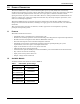
Specifications Table 17 Battery run times Number of Batteries/Cabinets Internal Battery Internal Battery + 1 External Battery Cabinet Internal Battery + 2 External Battery Cabinets Internal Battery + 3 External Battery Cabinets Liebert® GXT4™ Run Time, Minutes * Load Percent of Capacity 700VA 1000VA 1500VA 2000VA 3000VA 10% 105 91 112 81 91 20% 62 38 51 37 39 30% 37 31 34 23 23 40% 32 23 23 16 16 50% 27 17 18 12 12 60% 22 14 14 9 9 70% 18 11 11 7 7 8
Specifications Table 17 Battery run times (continued) Number of Batteries/Cabinets Internal Battery + 4 External Battery Cabinets Internal Battery + 5 External Battery Cabinets Internal Battery + 6 External Battery Cabinets * Run Time, Minutes * Load Percent of Capacity 700VA 1000VA 1500VA 2000VA 3000VA 10% 480 480 480 466 480 20% 480 460 444 421 423 30% 458 436 340 306 307 40% 442 340 309 192 192 50% 425 315 205 157 157 60% 336 218 165 142 143 70% 319 19
Specifications 9.1 Product Warranty Registration Registration is not required to activate the product warranty on a Liebert UPS. Registration is required to qualify for the Product Protection Promise. To register, visit the Emerson Network Power® Web site to fill out the online form at: www.emersonnetworkpower.com/en-US/Forms/Pages/LiebertProductWarrantyRegistration.aspx • To contact warranty support by e-mail: dpg.warranty@emerson.com 9.
Technical Support / Service Web Site www.liebert.com Monitoring liebert.monitoring@emerson.com 800-222-5877 Outside North America: +00800 1155 4499 Single-Phase UPS & Server Cabinets liebert.upstech@emerson.